Cylinder type gas heating stove heat flow field improvement structure

A technology of gas heating and improved structure, which is applied in the direction of air heaters, fluid heaters, heat storage heaters, etc., which can solve the problem of reducing the effective use of the heating surface and the heating surface, unable to realize the user's convective heat transfer mode, and not conducive to energy saving Consumption reduction and environmental protection and other issues, to achieve the effect of eliminating the dead angle of the heat flow field, simple structure, easy to popularize and use

Inactive Publication Date: 2012-01-25
SHANGHAI UNIV OF ENG SCI
View PDF2 Cites 0 Cited by
  • Summary
  • Abstract
  • Description
  • Claims
  • Application Information

AI Technical Summary

Problems solved by technology

[0007] a. Because the temperature of the medium close to the fire tube and the wall of the smoke tube bundle is high, an upward flow will be formed, while the temperature of the medium near the heated tube bundle is relatively low, and a downward flow will be formed, because there is no proper flow of the intermediate heat-carrying medium In addition, there is a temperature difference between the fire tube and the smoke tube bundle, and there is a temperature difference between the multiple returns of the heated tube bundle, all of which lead to the disorder of the flow field organization in the large cylinder, resulting in the heating of the large cylinder. Uneven; b. Due to the small temperature difference between the upper and lower sides of the flow field, the power of natural convection is also small, which makes it difficult to form an effective flow field, and the convective heat transfer between the heating surface and the heating surface in the large cylinder is very weak; c. In the whole In the flow field, there are still many flow dead angles, such as the bottom of the large cylinder, etc.
All these factors will destroy the effective heat transfer flow field in the large cylinder, reduce the effective utilization of the heating surface and the heating surface, thereby reducing the efficiency of the natural gas heating furnace and high energy consumption, which is not conducive to energy saving and environmental protection
d. In some occasions, such as when the difference between the heating temperature and the delivery temperature is small, because the flow field in the large cylinder is almost static, the heat transfer method is close to heat conduction. This is a method with poor heat transfer efficiency, and it cannot be achieved. The desired convective heat transfer method

Method used


Image

  • Cylinder type gas heating stove heat flow field improvement structure
  • Cylinder type gas heating stove heat flow field improvement structure
  • Cylinder type gas heating stove heat flow field improvement structure

Examples


Embodiment 1

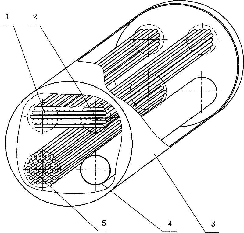
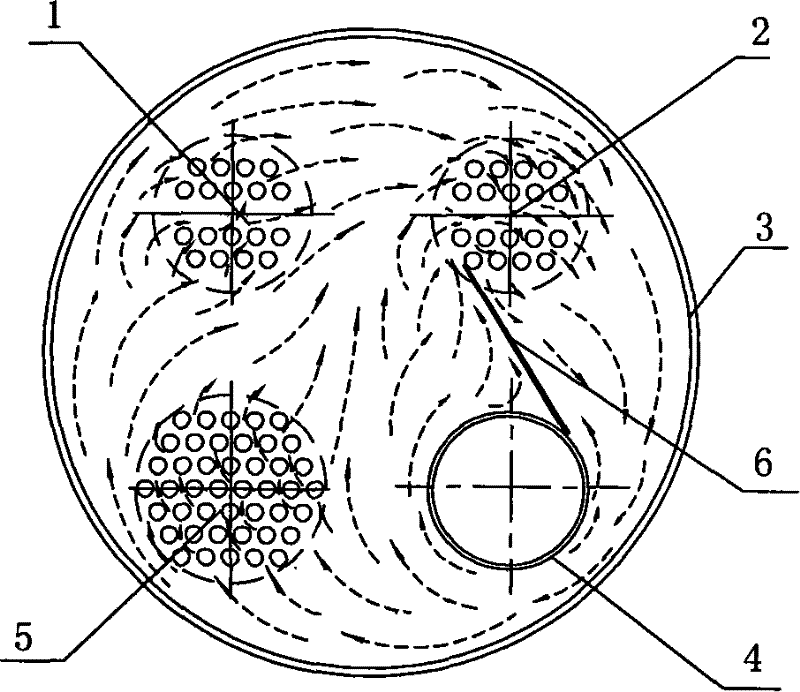
[0031] Depend on image 3As shown, in the large cylinder 3 with a length of 2.65 meters and a diameter of 1.22 meters, a flat-plate deflector is arranged along one side of the axial direction of the large cylinder, that is, between the heating gas feeding flow channel 4 and the heating gas sending flow channel required for transportation. 2, a single-side deflector 6 is set, and the heating surface and the heating surface in the large cylinder 3, due to the thermal pressure and the action of the deflector, make the intermediate heat-carrying medium form a heat flow field that circulates smoothly in a clockwise direction, eliminating "dead angles", Achieve enhanced heat transfer and uniform heating.

Embodiment 2

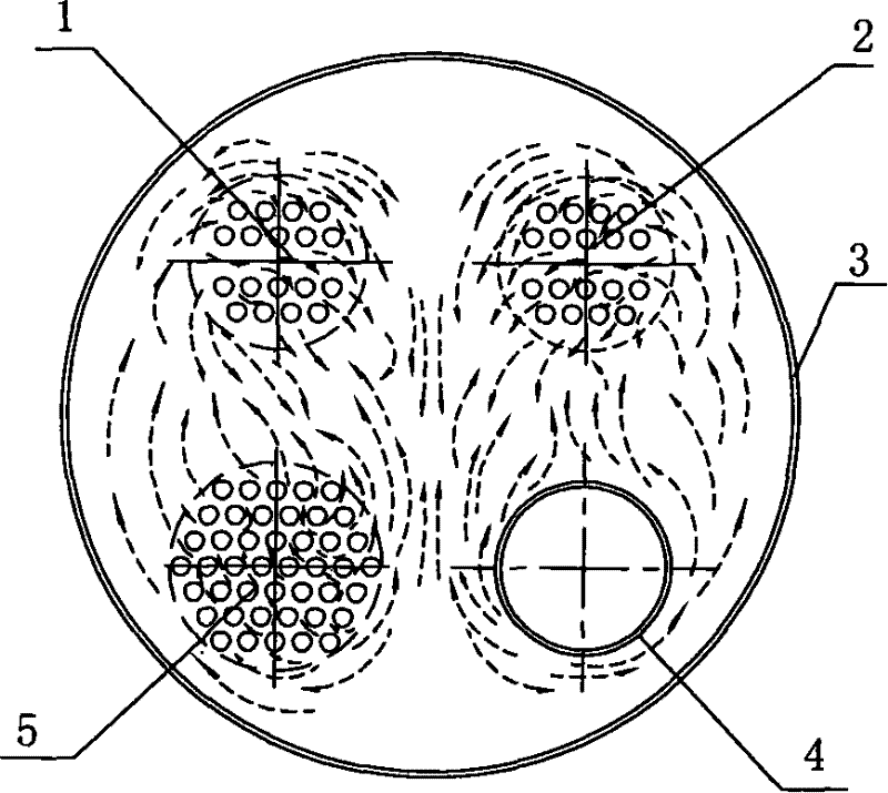
[0033] Depend on Figure 8 As shown, in the large cylinder 3 with a length of 2.65 meters and a diameter of 1.22 meters, flat-plate deflectors are arranged on both sides along the axial direction of the large cylinder, that is, when the heated gas is sent into the flow channel 4 and the heated gas is sent out of the flow channel required for transportation. 2 rooms, and the heating gas sending flow channel 5 and the heating gas sending channel 1 required for transportation, and a deflector 6 is arranged between the upper and lower flow channels corresponding to the left and right sides, and the configured deflector 6 The left side is up, right, down, left, and the right side is up, left, down, and right. The heating surface and the heating surface in the large cylinder 3 are thermally compressed and the deflectors make the middle heat-carrying medium form a heat flow field of two left and right eddy currents.


PUM


Abstract

The invention relates to a device for heating and heating up natural gas during the process of exploitation and distribution of the natural gas. The invention relates to an improved structure for a heat flow field of a cylindrical gas heating furnace, wherein, a flow channel is respectively arranged inside four quadrants of a cross section in a large cylinder (3), and two respective flow channelson the upper side and the lower side are communicated with each other on one end of the large cylinder (3); an opening on the other end of the large cylinder (3) is respectively provided with an inlet and an outlet; the two upper flow channels are flow channels for conveying heating gas to be heated and the two lower flow channels are heating gas flow channels; a heating gas feeding flow channel (4) on the lower side is a pipe structure, and both the two upper flow channels for conveying the heating gas to be heated and a heating gas delivery flow channel (5) on the lower side are pipe bundlestructures which consist of a plurality of tubules; the large cylinder (3) is filled with intermediate heating agents; and vertical guide plates are arranged along the flow channels between the upperflow channels for conveying the heating gas to be heated and the lower heating gas flow channels. By adoption of the technical proposal, the heating efficiency can be improved by approximately 3 percent.

Description

(1) Technical field [0001] The invention relates to a heating device for transporting gas, in particular to a device for heating and raising the temperature of natural gas in the process of natural gas exploitation, transmission and distribution. (2) Background technology [0002] Energy is an important pillar of national economic development and the basic guarantee for human survival. Clean energy is the fundamental way for the harmonious development of man and nature. Natural gas is an important clean energy endowed by nature to human beings. Therefore, its utilization technology has been widely valued by human beings. In the process of natural gas exploitation and long-distance transportation, due to various reasons, it is necessary to heat the large flow of high-pressure natural gas to prevent freezing. During use, when used in large gas-fired power plants, the natural gas must be heated to the specified temperature to achieve good results In natural gas oil and gas fie...

Claims


Application Information

Patent Timeline
Patent Type & Authority Patents(China)
IPC IPC(8): F24H7/02F24H3/08
Inventor 曹伟武严平郭韵钱尚源
Owner SHANGHAI UNIV OF ENG SCI
Why Eureka
Try Eureka