
Deformable lamp-cup type cold light lamp

A cold light lamp and lamp cup technology, applied in the direction of light source, electric light source, fixed light source, etc., can solve the problems of high use and maintenance cost, high infrared radiation, low light efficiency, etc., and achieve beautiful appearance, high light efficiency, uniform and bright illumination Effect

Active Publication Date: 2010-06-02
BEIJING XINGGUANG FILM & TV EQUIP TECH CO LTD
View PDF5 Cites 0 Cited by
  • Summary
  • Abstract
  • Description
  • Claims
  • Application Information

AI Technical Summary

Problems solved by technology

The disadvantages are low light efficiency, high energy consumption, high infrared radiation, short life, high maintenance cost

Method used


Image

  • Deformable lamp-cup type cold light lamp
  • Deformable lamp-cup type cold light lamp
  • Deformable lamp-cup type cold light lamp

Examples


Embodiment 1

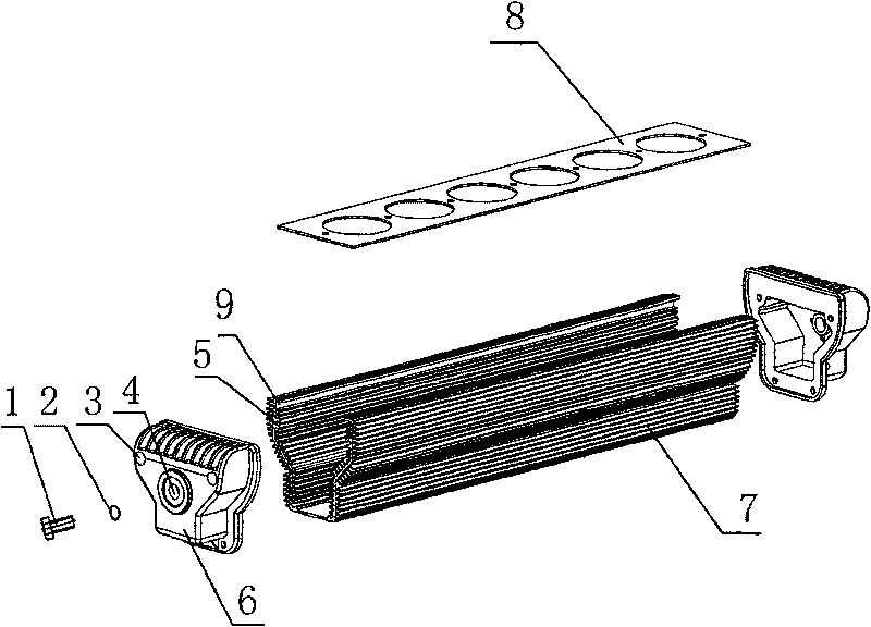
[0033] The deformable lamp cup type cold light lamp described in this embodiment, such as figure 1 , figure 2 , image 3 , Figure 4 , Figure 7 , Figure 8 As shown, it is composed of three single-group lights to form a rectangle. The single-group lights are composed of a housing 7, an end cover 6, a panel 8, and a cup bulb 13. The panel 8 is inserted into the slot 9 on the housing 7, and the two ends of the housing 7 Each end cover 6 is fixedly installed; there are 6 light source holes on the panel 8, and each cup 13 is put into the corresponding light source hole, and each cup 13 is connected in series with the power cord 10 through the lamp holder 14, and the combined It becomes a single-group lamp 11; the two end covers 6 of each single-group lamp are provided with lamp body connection holes 4, and the three single-group lamps are connected into a rectangle through the lamp body connection holes 4 with connectors.

[0034] The two ends of the power cord 10 pass thro...

Embodiment 2

[0043] The deformable lamp cup type cold light lamp described in this embodiment, such as figure 1 , figure 2 , image 3 , Figure 5 , Figure 6 As shown, it is composed of three single groups of lights to form a triangular shape. The single group of lights is composed of a housing 7, an end cover 6, a panel 8, and a cup bulb 13. The panel 8 is inserted into the slot 9 on the housing 7, and the two parts of the housing 7 One end cover 6 is fixed at each end; there are 6 light source holes on the panel 8, and each cup 13 is put into the corresponding light source hole, and each cup 13 is connected in series with the power cord 10 through the lamp holder 14, Combined into a single-group lamp 11; each single-group lamp is provided with a lamp body connection hole 4 on the two end covers 6, and the three single-group lamps are connected into a triangle through the lamp body connection hole 4 by a connecting piece.

[0044] The two ends of the power cord 10 pass through the tw...


PUM


Abstract

The invention relates to a cold light lamp with a deformable lamp cup. The cold light lamp comprises a plurality of single set lamps composing diversified shapes. The single set lamp comprises an outer casing, an end cover, a panel and a cup bulb. The panel is inserted into a slot on the outer casing, and an end cover is fixed at each of the two ends of the outer casing; a plurality of light source holes are provided on the panel, the cup bulbs are disposed into corresponding light source holes and are connected in series to compose a single set lamp; a lamp body connection hole is provided ateach of the two end covers of each single set lamp, a plurality of single set lamps are connected by using connectors to be a light apparatus with diversified shapes such as a triangle, a square, a rectangle or a polygon. The advantages of the invention are: the lamp body is made by combining aluminium section bars and casting dies, and is provided with attractive appearance, convenient connection, high intensity, good heat sinking and low cost; light source is a cold reflection directional halogen tungsten lamp cup bulb to reduce infrared radiation, and even and bright illumination is provided; 1-180 degrees expansion is provided between lamp bodies, and 360 degrees self rotation is provided with the lamp body; daisy chain assembly is provided according to performance requisition.

Description

technical field [0001] The invention belongs to stage lamps, in particular to a novel deformable cup-type cold light lamp for stage lighting and film and television. Background technique [0002] At present, there are many kinds of lamps and lanterns used in stage lighting and artistic performances, including spotlights, skylights, soft lights, and imaging lights. The disadvantages are low light efficiency, high energy consumption, high infrared radiation, short life, and high maintenance costs. Contents of the invention [0003] The object of the present invention is to provide a cup-type cold light lamp with novel appearance, simple structure, high energy saving and high light quality and good light quality. The shape of the lamp can be triangular, square, rectangular or polygonal. Infrared reflective cups and bubbles are combined into lamps. Regardless of the various shapes of this lamp, the total power is constant. [0004] The purpose of the present invention is ac...

Claims


Application Information

Patent Timeline
Patent Type & Authority Patents(China)
IPC IPC(8): F21S2/00F21S4/00F21V19/00F21V17/00F21W131/406F21K9/27F21K9/272
Inventor 甄何平李敬
Owner BEIJING XINGGUANG FILM & TV EQUIP TECH CO LTD
Learn More