Scroll-type compressor as well as floating mode for moving eddy disk and oil path control mode
A technology of scroll compressors and moving scrolls, which is applied in the field of scroll compressors, can solve problems such as reducing compression efficiency, and achieve the effects of reduced frictional power consumption, good durability, and simple and reasonable structure
- Summary
- Abstract
- Description
- Claims
- Application Information
AI Technical Summary
Problems solved by technology
Method used
Image
Examples
no. 1 example
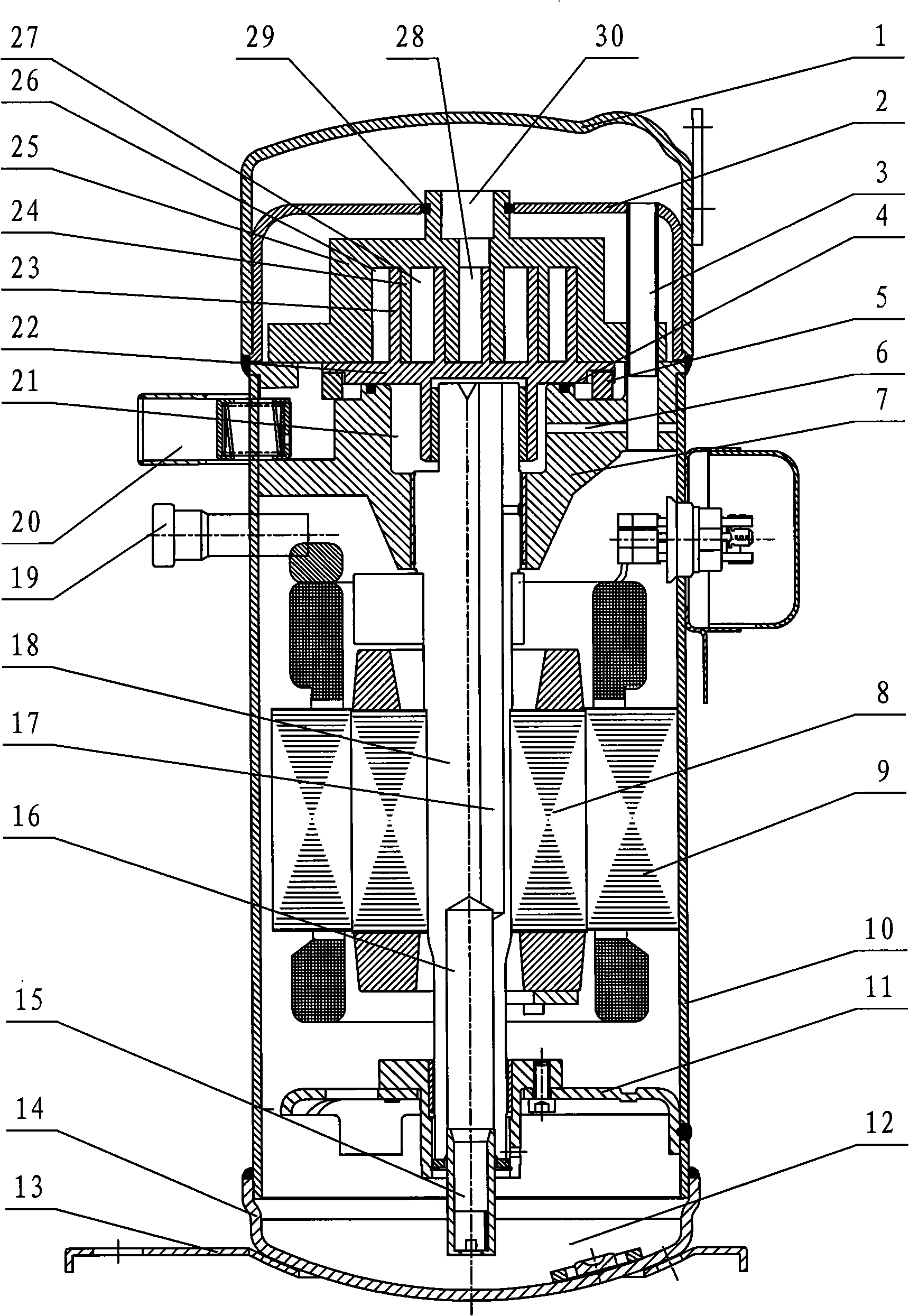
[0024] see image 3 In this scroll compressor, the main housing 10, the upper housing 1 and the lower housing 14 form a closed space through ring welding. The partition plate 2 and the upper casing 1 form a closed high-pressure area. The upper frame 7 and the main shell are welded together with the upper shell 1 through interference fit, so that a closed area is formed between the upper frame 7 and the partition plate 2, and the low-pressure fluid flows from the evaporator through the suction pipe 20 into the area. The movable scroll 22 revolves under the drive of the crankshaft 18 , and sucks the low-pressure fluid flowing in through the suction pipe 20 into the low-pressure chamber 26 . With the rotation of the crankshaft 18, the compression chamber formed between the movable scroll 22 and the fixed scroll 25 through the meshing of the scroll teeth 23 and 24 gradually compresses the low-pressure fluid into a high-pressure fluid, and in the central chamber 28 exhaust press...
no. 2 example
[0031] see Figure 5 , A high-pressure area is formed between the upper frame 7 and the upper casing 1 to accommodate the high-pressure fluid discharged from the exhaust port 30 of the fixed scroll 25 . Open grooves on the outer edges of the fixed scroll 25 and the upper frame 7 to guide the high-pressure fluid on the back side of the movable scroll to the high-pressure area where the motor is located. A sealing groove is provided on the upper frame to divide the back area of the movable scroll 22 into different pressure zones. A communication hole 6 is provided on the upper frame, and a medium-pressure area is formed in the back area 21 of the movable scroll 22 by using the drainage principle of high-speed fluid. Furthermore, the medium pressure is used to overcome the gas separation force borne by the movable scroll 22 during operation to realize the floating of the movable scroll 22, reduce the frictional power consumption between the movable scroll 22 and the upper fram...
no. 3 example
[0034] see Image 6 , A suction port is provided on the upper bracket, and a flange end cover 44 is used on the back of the fixed scroll 25 to seal the pit on the back of the fixed scroll. When the high-pressure gas is discharged from the exhaust port 30 on the back of the fixed scroll 25, it is directly discharged to the high-pressure area where the motor is located along the first gas guide channel 33.1 and the second gas guide channel 33.2. The method of opening a connecting hole on the upper frame is the same as Figure 4 , its working principle is the same as Figure 5 mentioned.
[0035] As mentioned above, the upper frame structure of the scroll compressor in the present invention, since a communication hole is provided between the guide passage of high-pressure gas and the pressure area on the back of the movable scroll, it can be installed on the back of the movable scroll. A medium-pressure area is formed, and because of the pressure difference between the two end...
PUM
 Abstract
Description
Claims
Application Information
 - R&D Engineer
- R&D Manager
- IP Professional
- Industry Leading Data Capabilities
- Powerful AI technology
- Patent DNA Extraction
Browse by: Latest US Patents, China's latest patents, Technical Efficacy Thesaurus, Application Domain, Technology Topic, Popular Technical Reports.
© 2024 PatSnap. All rights reserved.Legal|Privacy policy|Modern Slavery Act Transparency Statement|Sitemap|About US| Contact US: help@patsnap.com


