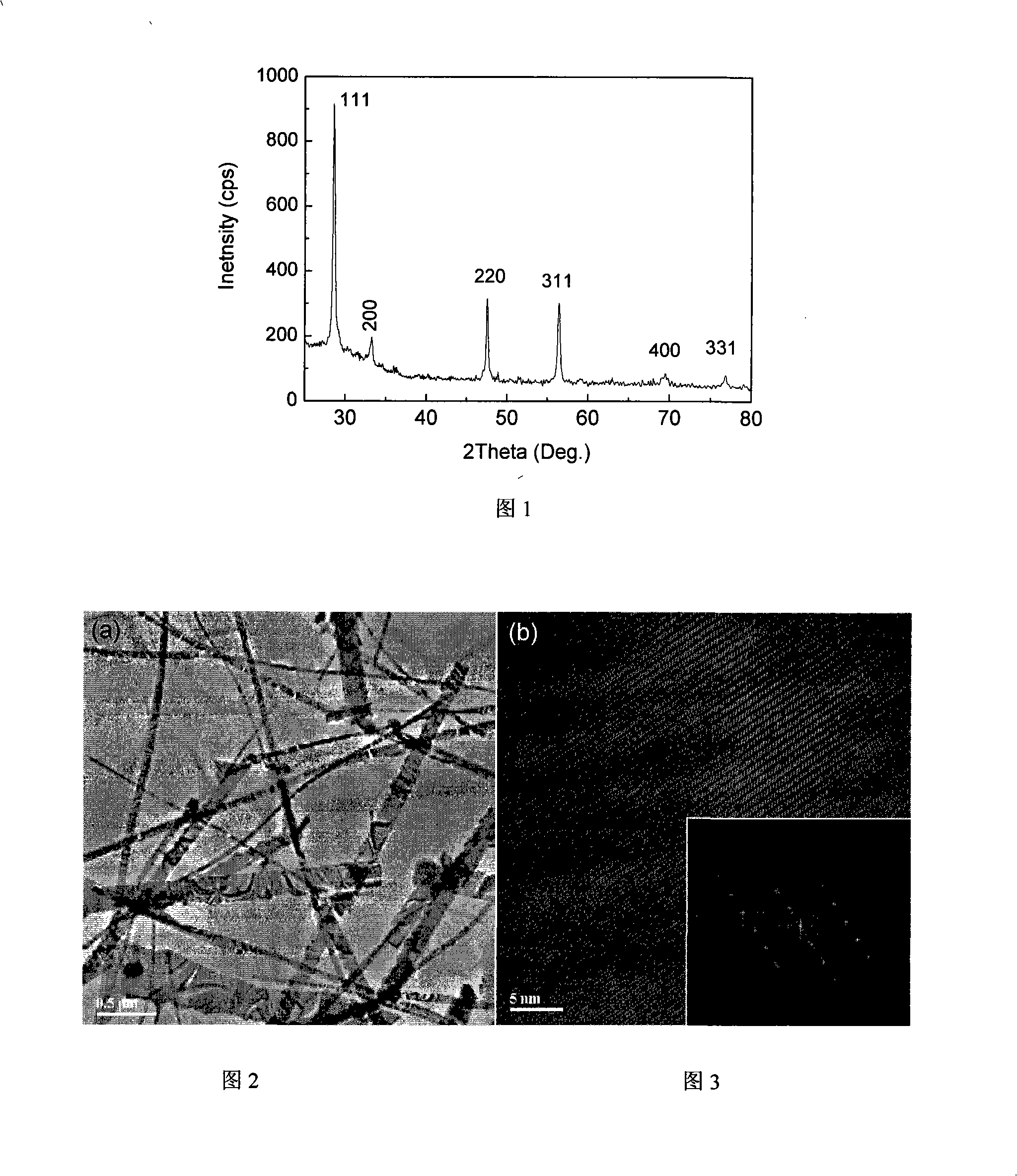
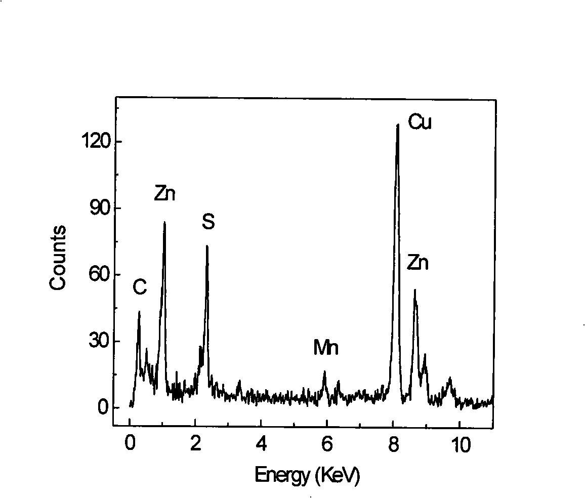
Method for preparing Mn-doped ZnS nanostructure
A nanostructure and argon gas technology, applied in the direction of zinc sulfide, etc., can solve the problems affecting the performance of Mn-doped ZnS nanomaterials, and achieve the effect of low cost and simple operation
- Summary
- Abstract
- Description
- Claims
- Application Information
AI Technical Summary
Problems solved by technology
Method used
Image
Examples
Embodiment 1
[0019] 1. Use a blank (no metallized film) silicon wafer as the receiving substrate. Silicon substrates were ultrasonically cleaned in alcohol and acetone, respectively.
[0020] 2. A mixed gas of argon and hydrogen with a flow rate of 110 ml / min (the volume ratio of hydrogen and argon is 10:100) is introduced into the tube furnace.
[0021] 3. ZnS powder and MnCl 2 The powder is placed in a quartz boat as an evaporation source, and the boat with the evaporation source and the cleaned silicon wafer are placed in a tube furnace. Wherein, the evaporation source is placed in the inlet direction of the argon-hydrogen mixed gas flow, the silicon chip is placed in the outlet direction of the argon-hydrogen mixed gas flow, and the horizontal distance between the silicon chip and the evaporation source is 4 mm.
[0022] 4. Raise the temperature of the tube furnace to 900°C, the holding time is 100min, and the pressure in the furnace is 0.015MPa. Cool down with the furnace after the...
Embodiment 2
[0025] 1. Use a blank (no metallized film) silicon wafer as the receiving substrate. Silicon substrates were ultrasonically cleaned in alcohol and acetone, respectively.
[0026] 2. A mixed gas of argon and hydrogen with a flow rate of 113 ml / min (the volume ratio of hydrogen and argon is 13:100) is fed into the tube furnace.
[0027] 3. ZnS powder and MnCl 2 The powder is placed in a quartz boat as an evaporation source, and the boat with the evaporation source and the cleaned silicon wafer are placed in a tube furnace. Wherein, the evaporation source is placed in the inlet direction of the argon-hydrogen mixed gas flow, the silicon chip is placed in the outlet direction of the argon-hydrogen mixed gas flow, and the horizontal distance between the silicon chip and the evaporation source is 3 mm.
[0028] 4. Raise the temperature of the tube furnace to 910°C, the holding time is 200min, and the pressure in the furnace is 0.015MPa. Cool down with the furnace after the growth...
Embodiment 3
[0030] 1. Use a blank (no metallized film) silicon wafer as the receiving substrate. Silicon substrates were ultrasonically cleaned in alcohol and acetone, respectively.
[0031] 2. A mixed gas of argon and hydrogen with a flow rate of 108 ml / min (the volume ratio of hydrogen and argon is 8:100) is introduced into the tube furnace.
[0032] 3. ZnS powder and MnCl 2 The powder is placed in a quartz boat as an evaporation source, and the boat with the evaporation source and the cleaned silicon wafer are placed in a tube furnace. Among them, the evaporation source is placed in the direction of the inlet of the argon-hydrogen mixed gas flow, the silicon chip is placed in the direction of the outlet of the argon-hydrogen mixed gas flow, and the horizontal distance between the silicon chip and the evaporation source is 6 mm.
[0033] 4. Raise the temperature of the tube furnace to 920°C, the holding time is 60min, and the pressure in the furnace is 0.03MPa. Cool down with the fur...
PUM
 Abstract
Description
Claims
Application Information
 - R&D
- Intellectual Property
- Life Sciences
- Materials
- Tech Scout
- Unparalleled Data Quality
- Higher Quality Content
- 60% Fewer Hallucinations
Browse by: Latest US Patents, China's latest patents, Technical Efficacy Thesaurus, Application Domain, Technology Topic, Popular Technical Reports.
© 2025 PatSnap. All rights reserved.Legal|Privacy policy|Modern Slavery Act Transparency Statement|Sitemap|About US| Contact US: help@patsnap.com


