
Optical head and apparatus for optically recording and reproducing information

A technology of information recording and optical head, which is applied in the direction of optical recording head, optical recording/reproduction, beam guiding device, etc., which can solve the problems of increased size, low utilization efficiency of main beam light, and complex detection optical system

Inactive Publication Date: 2008-08-27
HITACHI MEDIA ELECTORONICS CO LTD
View PDF2 Cites 3 Cited by
  • Summary
  • Abstract
  • Description
  • Claims
  • Application Information

AI Technical Summary

Problems solved by technology

Therefore, there is a problem that the detection optical system becomes complicated and the size increases
In Patent Document 2, the structure is such that a diffraction grating for generating three spots is arranged after the laser light source, and since one main spot and two sub spots are irradiated to the disk, there are The problem of low light utilization efficiency of the main beam necessary for recording
[0004] In CPM2005-149 (2005-10) (page 33, Fig. 4, Fig. 5) of the Institute of Electronics and Information and Communication Technology, since the focusing beam generated around the focusing photodetector comes from another layer On the outside of the diffused light, a photodetector for tracking is arranged, and the light diffracted at the center of the hologram (hologram) element reaches the outside of the diffused light from another layer, so the size of the photodetector increases. The problem

Method used


Image

  • Optical head and apparatus for optically recording and reproducing information
  • Optical head and apparatus for optically recording and reproducing information
  • Optical head and apparatus for optically recording and reproducing information

Examples


Embodiment 2

[0090] Embodiment 2 of the present invention will be described using FIGS. 12 to 15 .

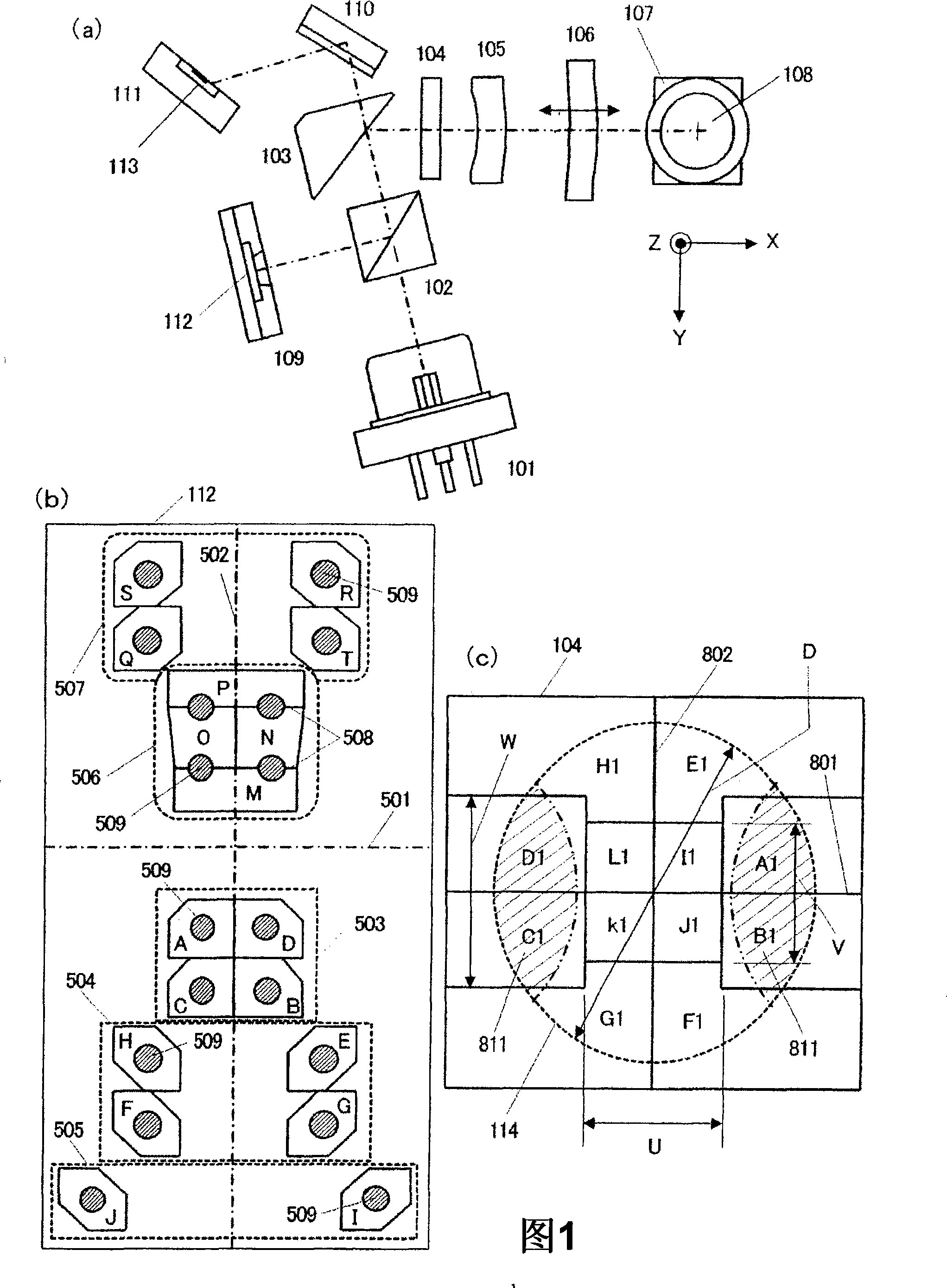
[0091] Fig. 12 is a top view schematically showing the optical head for BD in the embodiment. The difference from the first embodiment described with reference to FIG. 1 is that a condenser lens 1201 is arranged between the output surface 1202 of the polarizing beam splitter 102 and the BD photodetector 109 . Since everything else is the same as in Fig. 1, its description will be omitted.

[0092] Fig. 13 (a) shows, makes the magnification (composite focal length of BD auxiliary lens 105, BD collimator lens 106 and condenser lens 1201÷ The focal length of objective lens 108) is, from about 12 times of embodiment 1 (=outgoing system (outgoing system) magnification) to 10 times, 8 times, reduce, by grating surface A1 shown in Fig. 8 (a), grating surface The light beam diffracted by E1 is the result obtained by diffractive optical calculation with respect to the light beam image irradiated w...

Embodiment 3

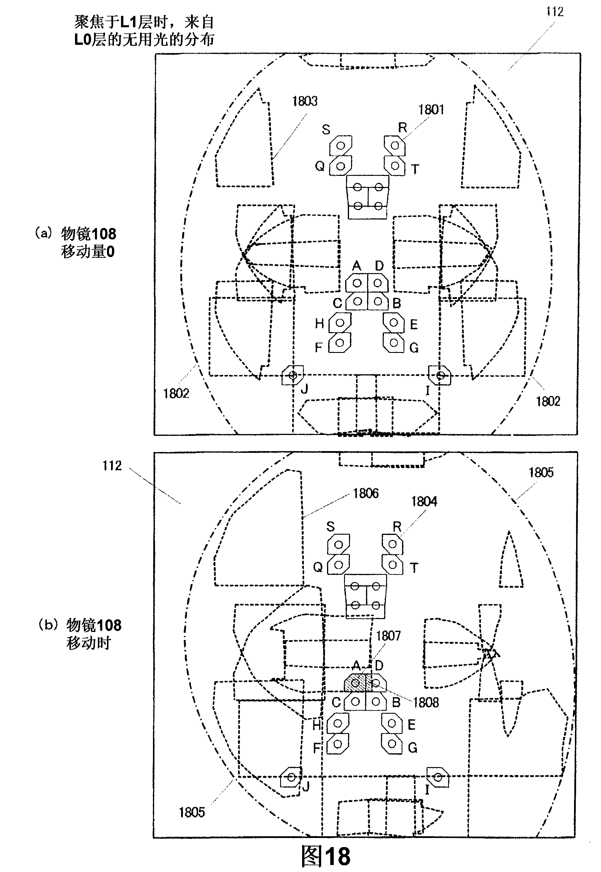
[0097] Embodiment 3 of the present invention will be described using FIGS. 16 to 18 .

[0098] FIG. 16 shows a light-receiving surface pattern of the light-receiving unit 112 of the BD photodetector 109 in this embodiment.

[0099] The difference from FIG. 5 of Embodiment 1 is that I leaves the direction of arrow 1602 and J leaves the direction of arrow 1601 to form a third light-receiving surface 1603 . In addition, I and J indicated by the dotted line indicate the position in FIG. 5 in the first embodiment. Since everything else is the same as in Fig. 5, its description will be omitted.

[0100] FIG. 17 shows the state of focusing on the target L0 layer in a BD information recording medium having two data layers of an L0 layer (cover layer thickness about 100 μm) and an L1 layer (cover layer thickness about 75 μm). The following is a calculation example of the distribution of unwanted light reflected from the L1 layer other than the target layer and irradiated to the light...

Embodiment 4

[0107] Embodiment 4 of the present invention will be described using FIGS. 19 to 21 .

[0108] FIG. 19 shows a grating pattern (lattice pattern) formed in the multi-beam splitting element 1901 in this embodiment, which is composed of a plurality of polarizing grating surfaces A1-D1, E2-L2. The difference from the multi-beam splitting element 104 shown in FIG. 8 in Embodiment 1 is that the shape of the first grating region composed of four polarizing grating surfaces I2, J2, K2, and L2 is the same as in the first embodiment. is a rectangle, and in this embodiment a rhombus (with 4 hypotenuses 1902). Along with this, the shape of the third grating region constituted by the four polarizing grating surfaces E2, F2, G2, and H2 is also different from that of the first embodiment. Since everything else is the same as the first embodiment described above, its description is omitted.

[0109] In this embodiment, the light-receiving surface pattern of the light-receiving unit 112 of t...


PUM

PropertyMeasurementUnit
diameteraaaaaaaaaa
diameteraaaaaaaaaa
thicknessaaaaaaaaaa

Abstract

The invention relates to an optical head and an apparatus for optically recording and reproducing information. A light receiving portion of a light detector comprises a first light receiving surface, a second light receiving surface, a third light receiving surface, a fourth light receiving surface and a fifth light receiving surface. The first light receiving surface is partitioned into pentagonal or hexagonal shapes, and the second, third and fifth light receiving surfaces are partitioned into hexagonal shapes. Furthermore, a relationship between a size of each of the light receiving surfaces and a diameter of respective one of light beams received by corresponding one of the light receiving surfaces is set within a predetermined range. A light beam multiple-dividing element diffracts the light beams received by a first grating area to form +primary lights, and diffracts the light beams received by second and third grating areas to form +primary lights and -primary lights. Relationships of U / D and V / D are set within predetermined ranges.

Description

technical field [0001] The present invention relates to an optical head and an optical information recording and reproducing device. Background technique [0002] As background art in this technical field, there is, for example, Japanese Patent Application Laid-Open No. 2006-344344. This gazette describes "acquiring a desired signal with high precision from an optical disc having a plurality of recording layers". Furthermore, there is, for example, Japanese Patent Laid-Open No. 2006-344380. This publication states that "even when an optical storage medium having two information recording surfaces capable of recording is used, a tracking error signal with a small offset can be detected". Furthermore, for example, it is described in CPM2005-149 (2005-10) (page 33, Fig. 4, Fig. 5 ) in Journal of Information Science and Technology of the Society of Electronics and Information Communication that "A photodetector for tracking is arranged in an area where there is no stray light ...

Claims


Application Information

Patent Timeline
Patent Type & Authority Applications(China)
IPC IPC(8): G11B7/135G11B7/13
CPCG11B7/0908G11B7/131G11B7/133G11B7/1353G11B7/1376G11B7/13925G11B2007/0006G11B2007/0013
Inventor 森弘充川村友人神定利昌
Owner HITACHI MEDIA ELECTORONICS CO LTD
Learn More