
Optical pick-up

A technology of optical pickup and equipment, applied in the direction of optics, optical components, optical recording heads, etc., can solve the problems of affecting servo signal, unable to complete recording, reproduction signal and servo signal noise

Inactive Publication Date: 2008-03-12
LG ELECTRONICS INC
View PDF0 Cites 3 Cited by
  • Summary
  • Abstract
  • Description
  • Claims
  • Application Information

AI Technical Summary

Problems solved by technology

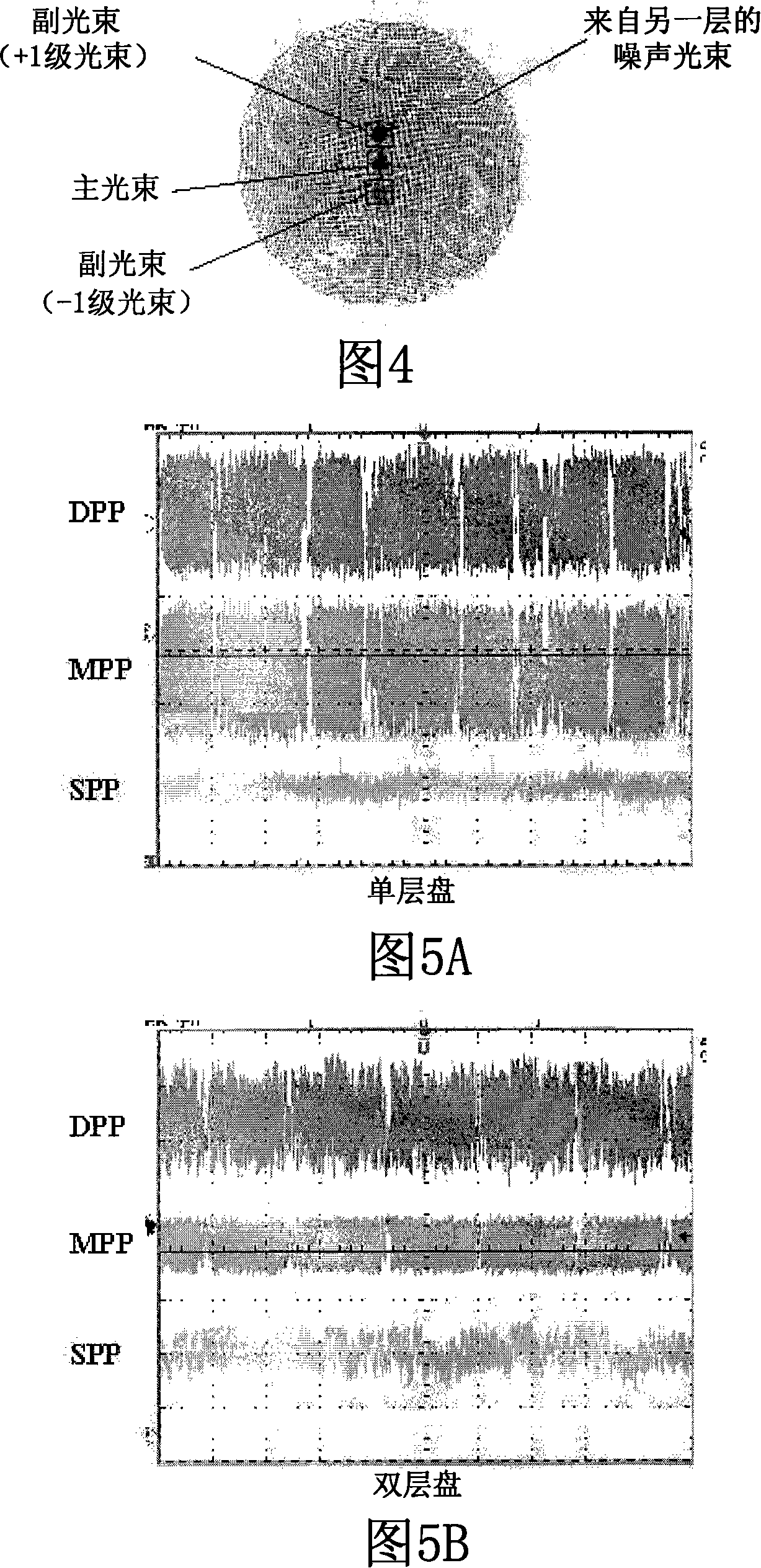
[0023] Noise light from another layer also flows into the main photodetector for receiving the main beam and the sub photodetector for receiving the sub beam, thereby affecting the servo signal as well as the reproduced signal
In particular, the servo signal obtained with a sub-beam with a small amount of light is greatly affected
[0024] As shown in Figures 5A and 5B, there is a problem that the SPP signal is excessively distorted due to noise light from another layer, and the DPP signal calculated based on the SPP signal, that is, the tracking error signal is degraded
That is, when an optical disc having two or more recording layers is reproduced or recorded, noise occurs in the reproduced signal and the servo signal due to a light beam reflected from another layer, as shown in FIGS. 4 and 5, and thus Reproduction or recording performance may deteriorate due to noise, and recording may not be completed in some cases

Method used


Image

  • Optical pick-up
  • Optical pick-up
  • Optical pick-up

Examples


Embodiment Construction

[0074] Embodiments of the present invention will be specifically described below with reference to the accompanying drawings.

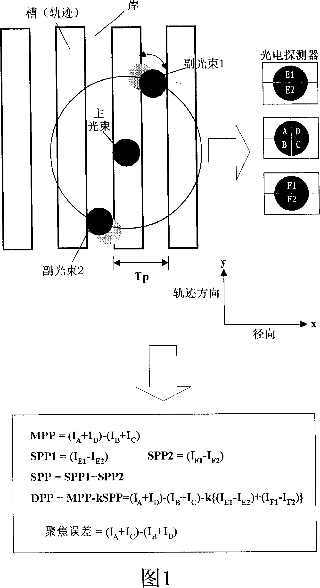
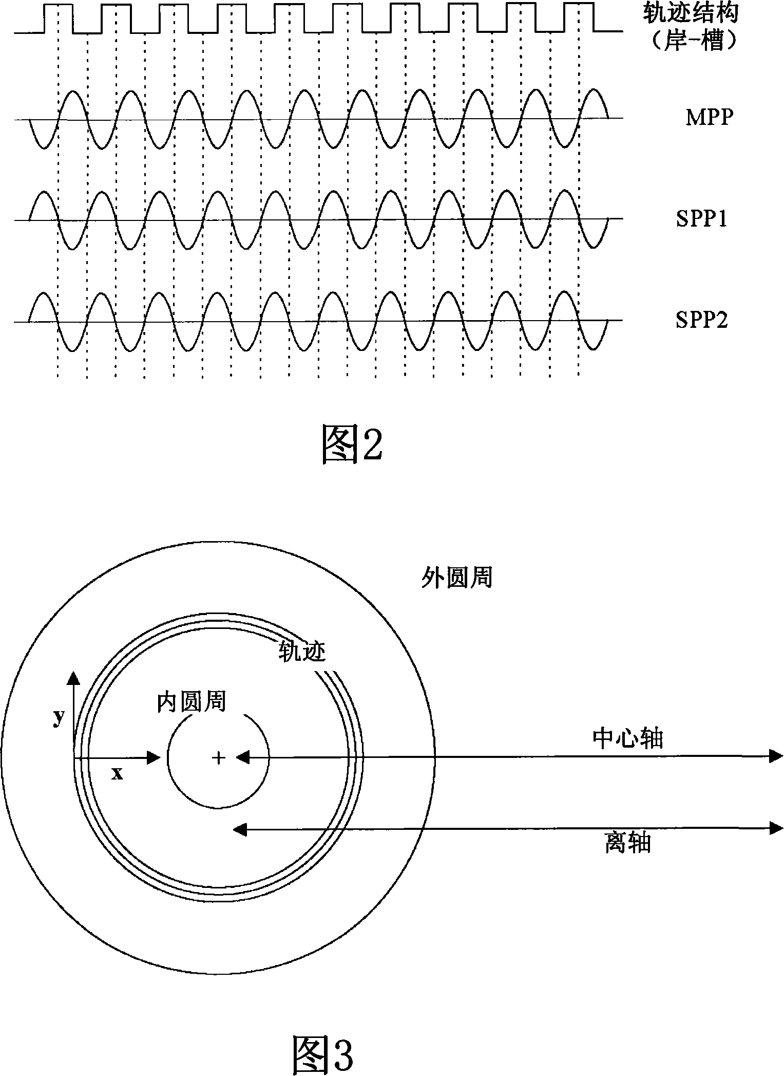
[0075] In the DPP method using 3 beams, the sub-beam is focused on the optical disc while being separated from the main beam by 1 / 2 the track pitch. In the typical case of disposing the objective lens on the central axis of the optical disk, the relative positions of the main beam and the sub-beam are not changed by the inner and outer circumferences of the optical disk.

[0076] However, in the case of an off-axis arrangement in which the objective lens operates off the central axis of the disc, as shown in FIG. In this case, there is a problem that, as shown in FIG. 6, at the boundary of the recording / non-recording area of ​​the optical disc, the deviation of the DPP signal increases, and the period during which the deviation occurs becomes long.

[0077]The difference between recorded and non-recorded areas is represented by the difference in thei...


PUM

PropertyMeasurementUnit
wavelengthaaaaaaaaaa

Abstract

An optical pickup is provided to obtain a stable error signal and to improve reproducing or recording performance thereof by decreasing interference between the layers of a multi-layered disc. An optical pickup(100) comprises a beam source(110), an objective lens(160), a beam splitter(130), a diffraction grating(140), a sensor lens(170), and an optical detecting unit(180). The beam source emits a beam with predetermined wavelength. The objective lens collects the beam emitted from the beam source at an optical storage medium. The beam splitter penetrates or reflects the beam emitted from the beam source, and the beam reflected at the optical storage medium. The diffraction grating diffracts a part of the beam passed through a first area, among the beams divided and reflected from the optical storage medium, and diffracts the part of the beam passed through a second area inside the first area at a position different from the position where the beam diffracted by the first area is focused. The sensor lens generates a luminous point at the beam reflected from the optical storage medium. The optical detecting unit includes a main detecting unit and two first sub detecting units. The main detecting unit receives the beam passed through the diffraction grating directly, and the two first sub detecting units receive the beam diffracted by the first area.

Description

technical field [0001] The present invention relates generally to an optical pickup device, and more particularly, to an optical pickup device capable of preventing noise generated in other layers from flowing into a servo signal. Background technique [0002] A compact disc (CD), an optical storage medium capable of storing up to 74 minutes of audio (music) or 650 megabytes of data, has held the record for two hours of standard-definition (SD)-level video since its introduction to the market. Digital Versatile Discs (DVDs) have been widely commercialized. In addition, in the near future, Blu-ray Disc (BD) or High Definition (HD) DVD capable of storing HD-level movies will enter the market. [0003] Optical storage media such as CD, DVD, and BD are disc-type media in which data is stored using optical properties, recorded on an optical disc, or reproduced by an optical pickup device. Optical storage media include discs for reproduction on which data is pre-recorded, and di...

Claims


Application Information

Patent Timeline
Patent Type & Authority Applications(China)
IPC IPC(8): G11B7/135G02B13/00G02B5/18G11B7/1353
CPCG11B7/0929G11B7/127G11B7/1353G11B7/1365G11B7/1374G11B7/1395
Inventor 任富彬
Owner LG ELECTRONICS INC
Learn More