
Method for manufacturing multilayered disk

a multi-layer disk and manufacturing technology, applied in the field of multi-layer disk manufacturing, can solve the problem of light reflected from an undesired layer being received by a photo detector, and achieve the effect of reducing the noise characteristics of all signals and reducing the interlayer interference of the multi-layer disk

Inactive Publication Date: 2009-09-22
LG ELECTRONICS INC
View PDF7 Cites 0 Cited by
  • Summary
  • Abstract
  • Description
  • Claims
  • Application Information

AI Technical Summary

Benefits of technology

The present invention provides a method for reducing interlayer interference in an optical pickup device by adjusting the range of a reflective signal. This is achieved by setting a space between the recording layers of a multilayered disk to less than 10 μm to refrain from interference when one of the layers is recorded or regenerated. The range of the reflective signal from the disk is preferably less than 1.7 μm, and the reflective signal is detected using an astigmatism method with a focus server. The method can also use a knife edge method or a foucault method for detecting the reflective signal. The technical effect of the invention is to decrease noise characteristics of all signals and improve the performance of the optical pickup device.

Problems solved by technology

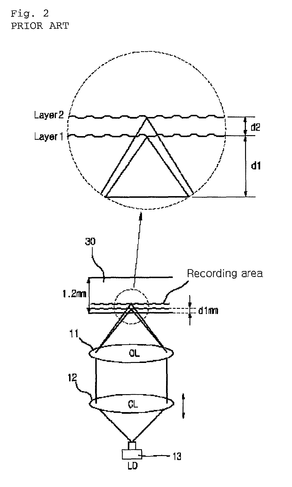
However, the most serious problem of the above described multilayered disk is that a light reflected from an undesired layer is received to a photo detector to operate as a noise when a laser light is condensed on a layer to be recorded or regenerated.

Method used


Image

  • Method for manufacturing multilayered disk
  • Method for manufacturing multilayered disk
  • Method for manufacturing multilayered disk

Examples


Embodiment Construction

[0028]Hereinafter, embodiments of the present invention will now be described in detail with reference to the attached drawings. Reference now should be made to the drawings, in which the same reference numerals are used throughout the different drawings to designate the same or similar components. In the following description of the present invention, detailed descriptions may be omitted if it is determined that the detailed descriptions of related well-known functions and construction may make the gist of the present invention unclear.

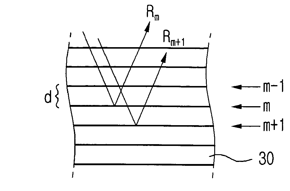
[0029]FIG. 3 shows an example of a reflective beam from a multilayered disk from which an interlayer interference is removed according to the present invention, and FIG. 4 shows the shape of a beam received from a photo detector according to the present invention.

[0030]Referring to FIGS. 3 and 4, when mth recording layer of the multilayered optical disk 30 in an optical pickup device is recorded or regenerated, the light is reflected on the (m+1)th l...


PUM

PropertyMeasurementUnit
sizeaaaaaaaaaa
storing densityaaaaaaaaaa
volumeaaaaaaaaaa

Abstract

The present invention relates to a method of manufacturing a multilayered disk capable of refraining from an interference at the adjacent layer when a specific layer of the multilayered layers is recorded or regenerated in an optical disk. According to the present invention, a method for manufacturing a multilayered disk having at least two recording layers is characterized by that a space between the two recoding layers is set to less than 10 μm to refrain from an interference at the adjacent layer when one of the recording layers is recorded or regenerated. According to a method for manufacturing a multilayered disk and a method for removing an interlayer interference using the disk in the present invention, it is possible to design and manufacture a multilayered disk within a reflective signal range.

Description

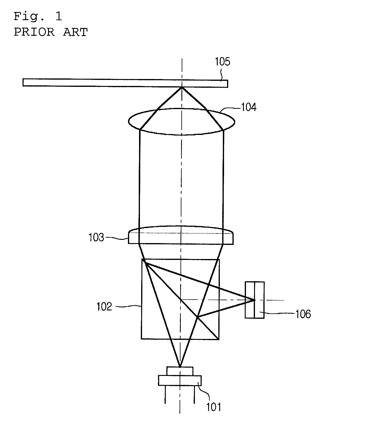
BACKGROUND OF THE INVENTION[0001]1. Field of the Invention[0002]The present invention relates to a method of manufacturing a multilayered disk capable of refraining from an interlayer interference between adjacent layers when a specific layer of the multilayered layers is recorded or regenerated in an optical disk.[0003]2. Background of the Related Art[0004]As a request for high quality moving pictures is increased in accordance with an improvement of consumers' lifestyle along with a speed doubling and an increase of storing density of an optical storing device, a larger volume of storing data of an optical storing disk is required.[0005]FIG. 1 is a schematic block diagram of a general optical pickup device.[0006]Referring to FIG. 1, the optical pickup device comprises a laser diode 101 emitting a beam with a regular wavelength, a beam splitter 102 reflecting or transmitting the beam, a collimator lens 103 emitting the beam impinged from the beam splitter 102 into a parallelized be...

Claims


Application Information

Patent Timeline
Patent Type & Authority Patents(United States)
IPC IPC(8): G11B7/24
CPCG11B7/26G11B2007/0013G11B7/24038
Inventor JEONG, SEONG-YUN
Owner LG ELECTRONICS INC
Learn More