Optical pickup apparatus
A technology of optical pick-up device and light source, applied in the direction of integrated optical head device, light beam source, optical recording head, etc., can solve the problems of difficult to obtain two-divided signal and unable to implement stable two-divided
- Summary
- Abstract
- Description
- Claims
- Application Information
AI Technical Summary
Problems solved by technology
Method used
Image
Examples
no. 1 approach
[0042] First, an optical pickup device according to a first embodiment of the present invention will be described.
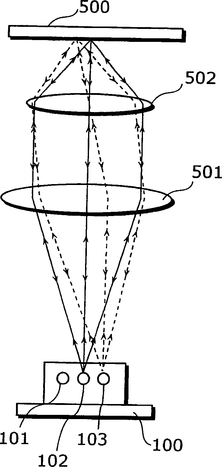
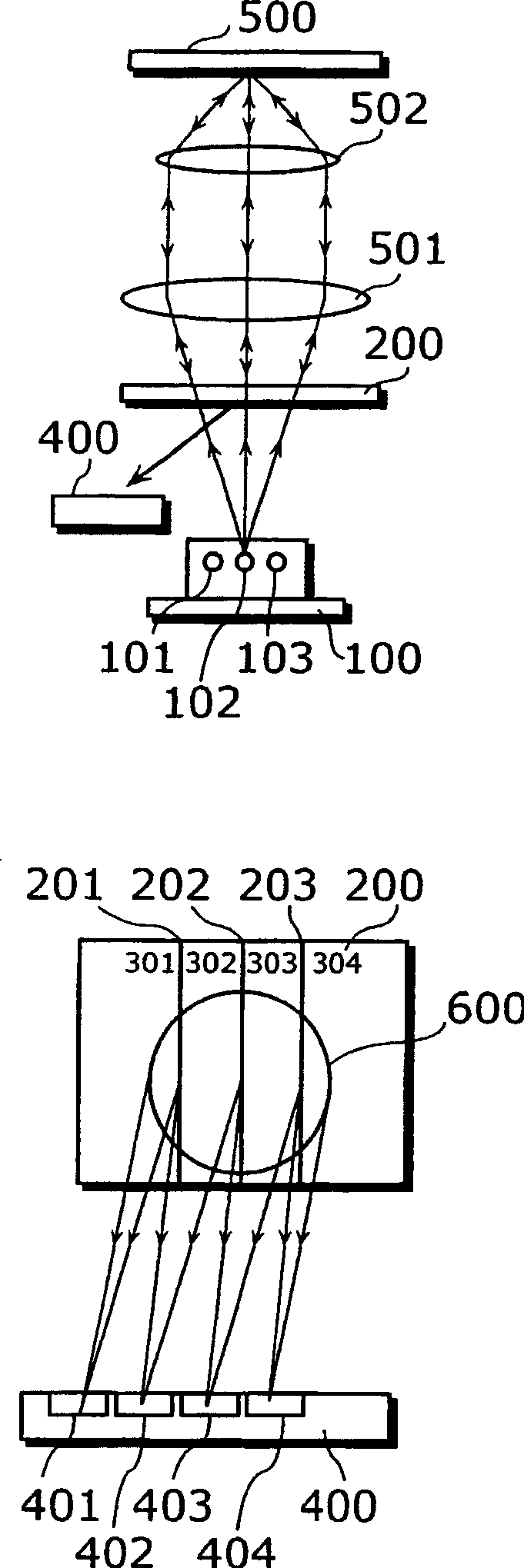
[0043] Figure 2A , Figure 2B , Figure 2C It is a configuration diagram showing the optical pickup device according to the first embodiment of the present invention, and an enlarged diagram showing the vicinity of the hologram element. The optical pick-up device includes a semiconductor laser element 100 with three light sources, a holographic optical element 200, a photosensitive element 400, an optical disc 500, a quasi-finger lens 501, and an objective lens 502, which are responsible for taking out information from the optical disc 500 or recording information to the optical disc. The holographic optical element 200 has separation lines 210 , 202 , and 203 at positions where light beams from the laser elements 101 , 102 , and 103 intersect the optical axes of the respective reflected lights reflected from the optical disc 500 .
[0044] Figure 2A , F...
no. 2 approach
[0058] Next, an optical pickup device according to a second embodiment of the present invention will be described.
[0059] Figure 3A , Figure 3B , Figure 3C It is a configuration diagram of an optical pickup device according to a second embodiment of the present invention, and an enlarged diagram of the vicinity of a hologram element thereof.
[0060] Compared with the optical pickup device of the first embodiment, the optical pickup device of the second embodiment has a beam splitter 503 and a detection lens 504 added. The same symbols are assigned to the same structures as those in the first embodiment, and explanations thereof are omitted.
[0061] The holographic optical element 200 has dividing lines 210 , 202 , 203 at positions intersecting the optical axis of light refracted by the light beams from the laser elements 101 , 102 , 103 reflected on the optical disk 500 by the beam splitter 503 . .
[0062] exist Figure 3A , Figure 3B , Figure 3C In FIG. 2 , ...
no. 3 approach
[0073] Next, an optical pickup device according to a third embodiment of the present invention will be described.
[0074] Figure 4A , Figure 4B , 4C It is a configuration diagram of an optical pickup device according to a third embodiment of the present invention, and an enlarged diagram of the vicinity of a hologram element thereof. Members of the present embodiment are the same as those of the optical pickup device of the first embodiment, and are given the same reference numerals, and description thereof will be omitted.
[0075] exist Figure 4A , Figure 4B , 4C In FIG. 2 , the light beam emitted from the semiconductor laser element 100 having three light sources 101 , 102 , and 103 is combined with the optical disc through a condensing optical system composed of a collimator lens 501 and an objective lens 502 . As an example, the optical system coincides with the optical axis of the central light source 102 among the three light sources of the semiconductor lase...
PUM
 Abstract
Description
Claims
Application Information
 - R&D
- Intellectual Property
- Life Sciences
- Materials
- Tech Scout
- Unparalleled Data Quality
- Higher Quality Content
- 60% Fewer Hallucinations
Browse by: Latest US Patents, China's latest patents, Technical Efficacy Thesaurus, Application Domain, Technology Topic, Popular Technical Reports.
© 2025 PatSnap. All rights reserved.Legal|Privacy policy|Modern Slavery Act Transparency Statement|Sitemap|About US| Contact US: help@patsnap.com


