
Dart carded felt guillotine

A cutting machine and felt technology, which is used in the cutting of textile materials, textiles and papermaking, metal processing and other directions, can solve the problems of inability to guarantee the quality of needle-punched felt incisions, fragile and felt incisions, and short service life of hob, etc. Achieve excellent self-cooling effect, save complicated work, and ensure the effect of production efficiency

Active Publication Date: 2008-08-27
JIANGSU YINGYANG NONWOVEN MASCH CO LTD
View PDF0 Cites 28 Cited by
  • Summary
  • Abstract
  • Description
  • Claims
  • Application Information

AI Technical Summary

Problems solved by technology

[0004] The needle felt cutting machine with the above-mentioned structure mainly exposes the following shortcomings during use: First, the service life of the hob is short, and it usually needs to be changed every shift (8h), because the disc-shaped hob is heated after passing through. When the needle-punched felt with a high hardness and a thickness of about 0.4-0.8cm after forming treatment is rolled and cut, it will generate heat and heat due to the friction between it and the felt, and the hob will quickly passivate and deform; the second is The incision quality of needle-punched felt cannot be guaranteed, and the hob is very easy to damage the incision of the felt under the condition of heat or even heat, which may deform the incision in mild cases, and cause the incision part of the felt to be scorched in severe cases; the third is that the cutting efficiency is low, Because changing the knife every shift will delay the continuous production, and the cost of using the hob is high, and in order to avoid damage to the needled felt caused by the hot hob, it is usually a last resort to stop the hob halfway. Knife moderate cooling

Method used


Image

  • Dart carded felt guillotine
  • Dart carded felt guillotine
  • Dart carded felt guillotine

Examples


Embodiment Construction

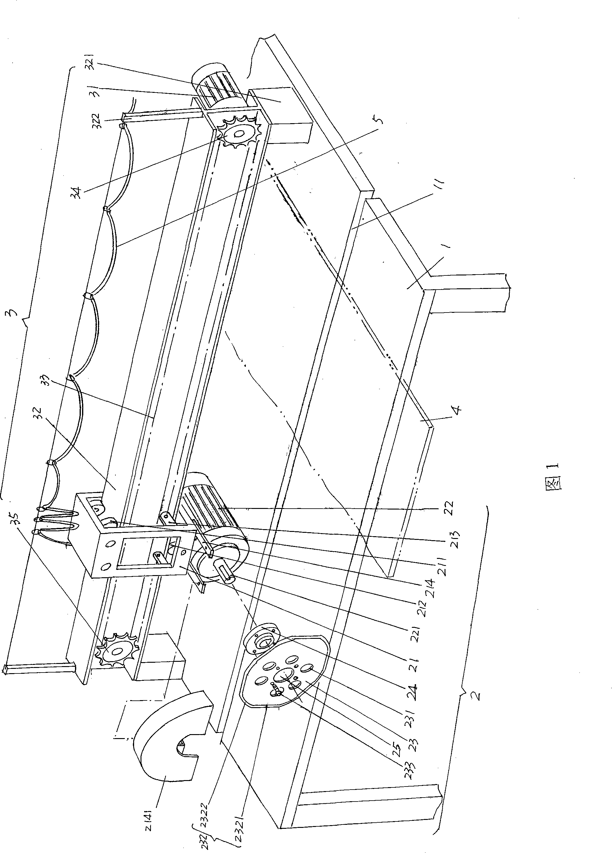
[0021] Please see Fig. 1, according to the common sense known in the industry, the needle felt cutting mechanism of the present invention is equipped next to the needle felt forming processing machine at the needle felt production site, and enters the needle punching machine after the needle punching is completed. The felt forming processor handles, and the felt 4 with a thickness of 0.4-0.8cm is usually fed to the cutting table 1 of the present invention, and a hob groove 11 is preset on the cutting table 1. Seen from the figure, the hob The slot 11 is opened in the width direction of the cutting table 11, and is offset from one end (the outlet end) of the cutting table 11.

[0022] The traction motor 31 of the traction mechanism 3 is a positive and negative motor, which is installed and fixed on one end of the guide rail 32, that is, installed on the right end of the current illustrated position state, and the cross-section shape is preferably two sides of the guide rail 32 o...


PUM


Abstract

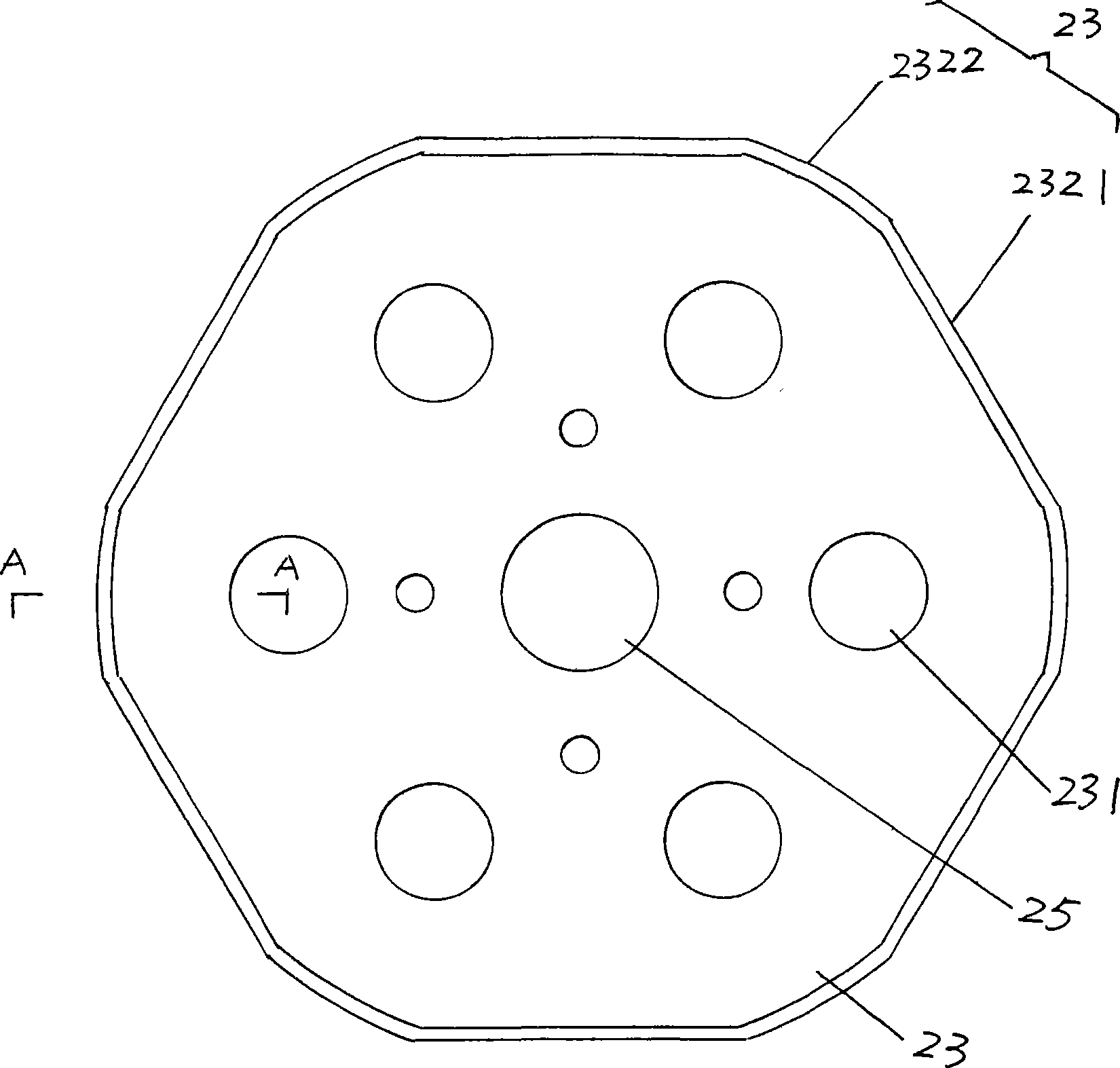
Disclosed is a needled felt cutting machine belonging to the technical field of non-woven machineries, which comprises a cutting table which is provided with a hob cutter groove, a cutting mechanism which comprises a hob cutter motor, a hob cutter motor seat and a hob cutter and a traction mechanism which is fixed on the cutting table, wherein the hob cutter motor is fixed on the hob cutter motor seat which is glidingly matched on the traction mechanism, the hob cutter is fixed on a power take-off shaft of the hob cutter motor and is corresponded with the hob cutter groove, and cutting edges of the hob cutter are made of a plurality of straight flange cutting edges and a plurality of circular cutting edges in alternate spreading with each other. The needled felt cutting machine has the advantages of representing intermittent suspension process when the hob cutter cuts the needled felt, thereby being unable to arose heating and insuring that a cut is not deformed and charred, not only saving numerous operations for exchanging the hob cutter every day and the numbers of usage of the hob cutters, but also guaranteeing productive efficiency, and being capable of increasing operating life of the hob cutter and improving the cut quality of the needled felt.

Description

technical field [0001] The invention relates to a needle-punched felt cutting machine, which is an improvement to the needle-punched felt cutting machine in the prior art, and belongs to the technical field of non-woven machinery. Background technique [0002] Needle-punched felt is a non-woven product made by needle-punching the main component of hemp fiber and the auxiliary component of chemical fiber such as polyester and / or acrylic fiber by a needle punching machine. Materials such as car roofs (also known as ceilings). Needle-punched felt products usually need to be cut according to the specifications of users such as automobile manufacturers when they leave the factory, that is to say, after the previous needle-punching operation is completed, they will be shaped by a forming machine and then cut. The so-called forming treatment refers to heat-pressing the needle-punched felt to form a shape, and at the same time compound a layer of plastic film on at least one surfac...

Claims


Application Information

Patent Timeline
Patent Type & Authority Applications(China)
IPC IPC(8): D06H7/00B26D1/56
Inventor 王皓王竞范立元
Owner JIANGSU YINGYANG NONWOVEN MASCH CO LTD
Learn More