
Relay valve

A relay valve and valve body technology, applied in the direction of brakes, brake components, control valves and air release valves, can solve the problems of unfavorable braking of heavy vehicles

Inactive Publication Date: 2008-08-27
傅晓辉 +2
View PDF0 Cites 8 Cited by
  • Summary
  • Abstract
  • Description
  • Claims
  • Application Information

AI Technical Summary

Problems solved by technology

Therefore, the use of this type of relay valve is unfavorable for the braking of heavy vehicles, especially when the vehicle is overloaded or overspeed.

Method used


Image

  • Relay valve

Examples


Embodiment Construction

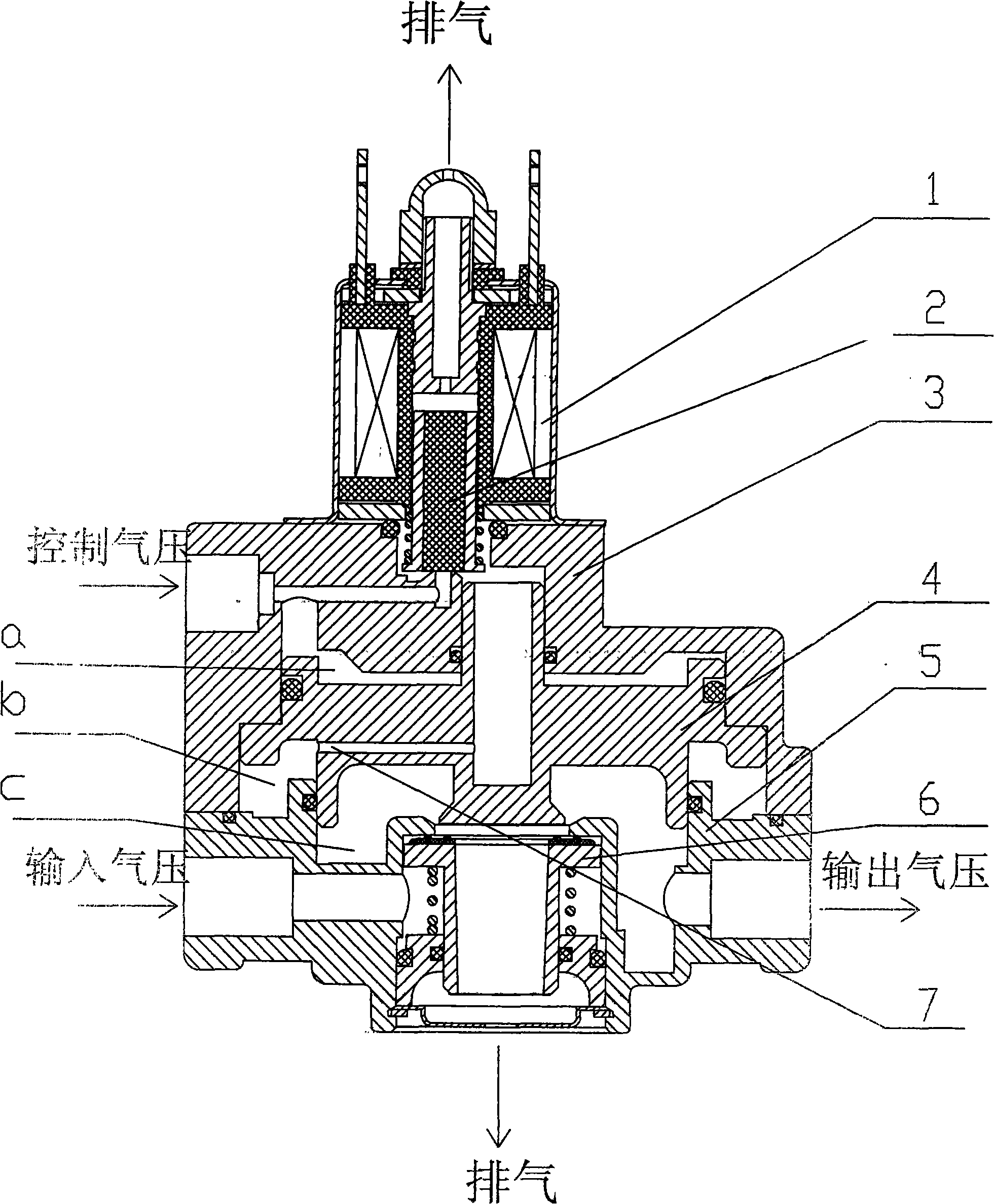
[0010] exist figure 1 Among them, when the vehicle is unloaded, a relay valve of the present invention acts as a general relay valve. At this time, the solenoid valve works, and the core rod 2 of the solenoid valve 1 moves away from the valve port at the lower end and seals the solenoid valve. The vent hole on the top, the control air pressure enters the air cavity 1 from the control air pressure inlet and passes through the middle cavity of the piston 4, and then enters the air cavity 2 through the small hole 7. Under the action of the air pressure, the piston 4 moves down to open the valve 6, input After the air pressure enters the air chamber 3, it forms an output air pressure to the brake cylinder; due to the counteracting effect of the air chamber 2, the upper and lower acting areas of the piston 4 are nearly equal, and the output air pressure is close to the control air pressure. At this time, the relay valve is different from the general relay valve. Works the same.

...


PUM


Abstract

The invention relates to a relay valve, in particular to a relay valve used in automobiles, which comprises a valve body assembly, valve bonnet, pistons and the like. The valve body assembly is provided with an input air pressure inlet, an output air pressure opening, an air exhaust opening, a valve and a spring. The valve bonnet is provided with a control air pressure inlet. The valve body assembly and the valve bonnet are internally provided with pistons. An air cavity 3 is formed between the valve body assembly and the pistons. An air cavity 1 is formed between the valve bonnet and the pistons. An air cavity 2 is formed among the valve body assembly, the valve bonnet and the pistons. An electromagnetic valve arranged on the valve bonnet is provided with an air vent. The air cavity 2 iscommunicated with a control air pressure cavity arranged on the valve bonnet or the air vent arranged on the electromagnetic valve which is disposed on the valve bonnet, and is controlled by the electromagnetic valve. When vehicles are in idle load, the electromagnetic valve is in work and the relay valve of the invention works as the ordinary relay valve. When the vehicles overload, the electromagnetic valve does not work. And the settling time of the pressure of a brake cylinder can be largely shortened through the effect of the air cavity 2, and the relay valve acts in amplification. The case is very beneficial to the vehicles which overload, in particular to braking for overloading and overspeed.

Description

technical field [0001] The invention relates to a relay valve, in particular to a relay valve used in automobiles. Background technique [0002] In the braking system of trucks, the relay valve plays the role of shortening the reaction time and pressure build-up time. A relay valve is used at the end of the long line to quickly fill the brake chamber with compressed air from the air reservoir. The control air pressure for the relay valve comes from the brake master cylinder (tandem valve or dual chamber brake valve). Since the pipeline from the brake master cylinder to the relay valve is relatively long, and there is a partial pressure loss in the long pipeline, the control air pressure of the relay valve acting on the rear brake is established slowly; while the brake air pressure of the front brake comes directly from For the brake master cylinder, the air pipe is relatively short, the air pressure builds up quickly and the loss is small. However, the output air pressure...

Claims


Application Information

Patent Timeline
Patent Type & Authority Applications(China)
IPC IPC(8): B60T15/18
Inventor 傅晓辉鲍绍建楼钟华
Owner 傅晓辉
Learn More