Reinforced concrete structure with steel plate reinforcement layer set on partial surface

A reinforced concrete and reinforced layer technology, applied in the field of reinforced concrete structures, can solve problems affecting structural safety and durability, reduce structural rigidity and durability, increase section size, etc., to reduce control section size, reduce Crack width, effect of increasing joints

Inactive Publication Date: 2011-06-01
CHONGQING JIAOTONG UNIVERSITY
View PDF0 Cites 0 Cited by
  • Summary
  • Abstract
  • Description
  • Claims
  • Application Information

AI Technical Summary

Problems solved by technology

The existence of cracks obviously reduces the rigidity and durability of the structure, which greatly limits its practical range. Therefore, improving the crack resistance of reinforced concrete structures has become a goal pursued by engineers all over the world. For this reason, people have developed and practiced prestressing. Concrete structure can better solve the problem of crack resistance of long-span concrete structures, but it can solve the tension problem of concrete in local areas under complex conditions (such as the top of the concrete unhinged arch foot section and the top of the continuous beam middle support section). Usually the tensile stress is relatively large, but it changes to compressive stress after a short section) so far there is no good solution, so that the section size of the entire component is increased due to the crack resistance requirements of the local control area, resulting in damage to most beams. Waste in terms of segments, otherwise structural cracks will appear, affecting the safety and durability of the structure

Method used


Image

  • Reinforced concrete structure with steel plate reinforcement layer set on partial surface
  • Reinforced concrete structure with steel plate reinforcement layer set on partial surface
  • Reinforced concrete structure with steel plate reinforcement layer set on partial surface

Examples


Embodiment 1

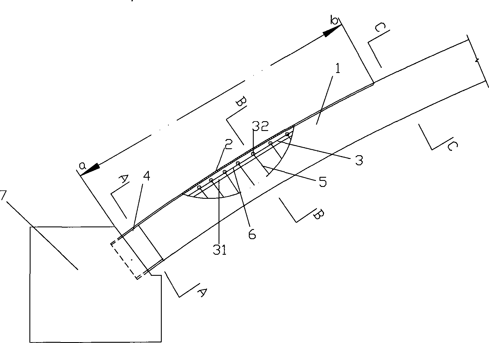
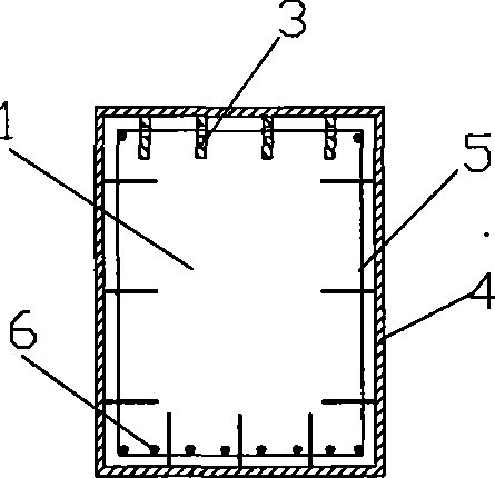
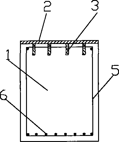
[0026] figure 1 It is a structural schematic diagram of Embodiment 1 of the present invention, figure 2 for figure 1 View along A-A direction, image 3 for figure 1 View along B-B direction, Figure 4 for figure 1 Sectional view along C-C direction, Figure 5 It is a schematic diagram of the force analysis of the invention embodiment 1, as shown in the figure: the reinforced concrete structure of the partial surface of the present embodiment is provided with a steel plate reinforcement layer as an arch rib, including a reinforced concrete arch rib 1, a stirrup 5 poured in the arch rib and a longitudinal The steel bar 6 is poured on the upper surface of the reinforced concrete arch rib 1 that bears the tensile stress, and the steel plate reinforcement layer 2 is cast as a whole; the lower end of the steel plate reinforcement layer 2 is fixedly connected with the abutment 7 through the steel box 4, and the steel box 4 Enclosed around the root of the reinforced concrete ar...

Embodiment 2

[0031] Image 6 Schematic diagram of the second embodiment of the present invention, Figure 7 for Image 6 Sectional view along D-D direction, Figure 8 for Image 6 Sectional view along E-E direction, Figure 9 for Image 6 Sectional view along F-F direction, Figure 10 It is a schematic diagram of the force analysis of the second embodiment of the invention, as shown in the figure: the reinforced concrete structure with a steel plate reinforcement layer on the local surface of this embodiment is a continuous beam structure, including a reinforced concrete continuous beam structure 1, and a stirrup 5 poured in the continuous beam structure and the longitudinal steel bar 6, the upper surface of the continuous beam structure at the upper surface of the continuous beam structure 1 that bears the tensile stress on the upper part of the reinforced concrete continuous beam structure 1 is poured to form a steel plate reinforcement layer 2, and the two ends of the steel plate r...


PUM


Abstract

The invention discloses a reinforced concrete structure, part of the surface of which is provided with a steel plate reinforced layer, comprising a reinforced concrete structure body; the surface of the section bearing tensile stress of the reinforced concrete structure body is poured into an integrated steel plate reinforced layer; the invention can obviously improve the crack resistance bendingmoment of the reinforced concrete structure, enhance the load capacity and ductility and shock resistance capacity of the reinforced concrete structure, restrain the increasing speed of the crack, reduce the width of the crack greatly, and improve the safety and the durability of the reinforced concrete structure effectively.

Description

technical field [0001] The invention belongs to the technical field of building structures, and in particular relates to a reinforced concrete structure with steel plate reinforcing layers on the local surface. Background technique [0002] Reinforced concrete has the advantages of local materials, simple construction, strong moldability, and low cost. So far, it has been widely used in buildings and bridge structures around the world. However, due to the extremely low tensile strength of concrete, ordinary reinforced concrete structures usually work with cracks. The existence of cracks obviously reduces the rigidity and durability of the structure, which greatly limits its practical range. Therefore, improving the crack resistance of reinforced concrete structures has become a goal pursued by engineers all over the world. For this reason, people have developed and practiced prestressing. Concrete structure can better solve the problem of crack resistance of long-span concr...

Claims


Application Information

Patent Timeline
Patent Type & Authority Patents(China)
IPC IPC(8): E04B1/00E04B1/32E01D19/00E01D4/00E04C3/00
Inventor 周志祥徐勇
Owner CHONGQING JIAOTONG UNIVERSITY
Why Eureka
Try Eureka