Method, device and system for transmitting Ethernet signals in optical transmission network

An optical transport network, Ethernet technology, applied in the direction of transmission system, optical multiplexing system, multiplexing system selection device, etc., can solve the problems of wasted bandwidth, bandwidth waste, low transmission efficiency, etc. The effect of wavelength, reducing transmission cost and improving bandwidth utilization

Active Publication Date: 2008-08-13
HUAWEI TECH CO LTD
View PDF0 Cites 11 Cited by
  • Summary
  • Abstract
  • Description
  • Claims
  • Application Information

AI Technical Summary

Problems solved by technology

[0007] However, after in-depth research by the inventor, it is found that the above two methods have certain defects
The method of adapting 100GE signal to OPU2-11v by adapting 100G bandwidth signal to 11×2.5G bandwidth wastes about 9.95G bandwidth; and occupies 11 color wavelengths, resulting in high transmission cost
The method of adapting 100GE signal to OPU3-3v adapts 100G bandwidth signal to 3×40G bandwidth, resulting in a huge waste of about 20.45G bandwidth and low transmission efficiency

Method used


Image

  • Method, device and system for transmitting Ethernet signals in optical transmission network
  • Method, device and system for transmitting Ethernet signals in optical transmission network
  • Method, device and system for transmitting Ethernet signals in optical transmission network

Examples


Embodiment Construction

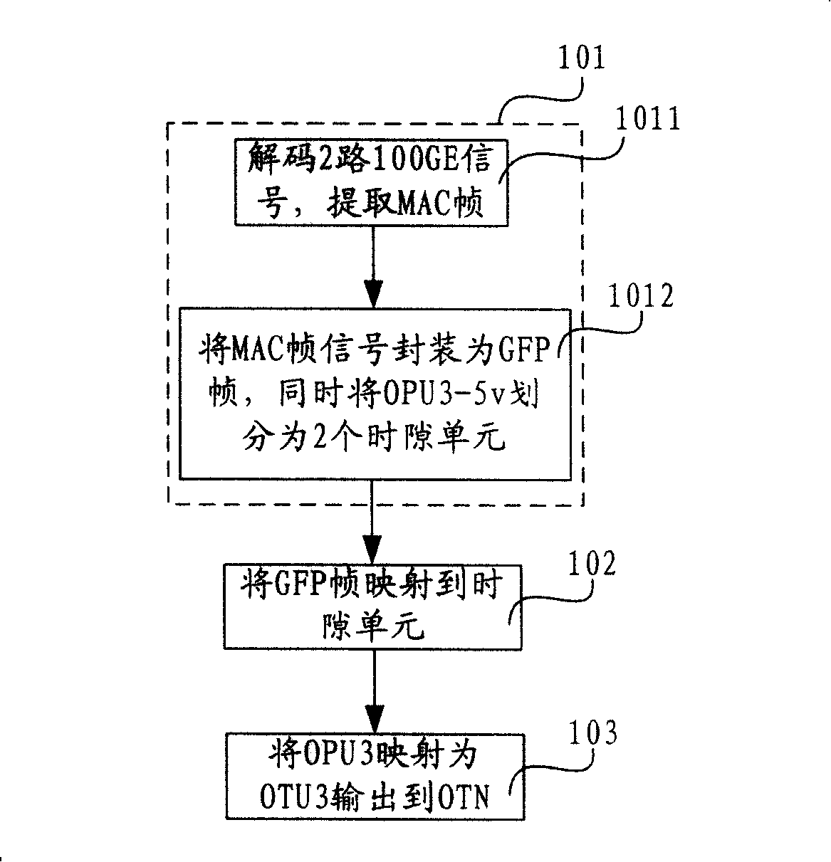
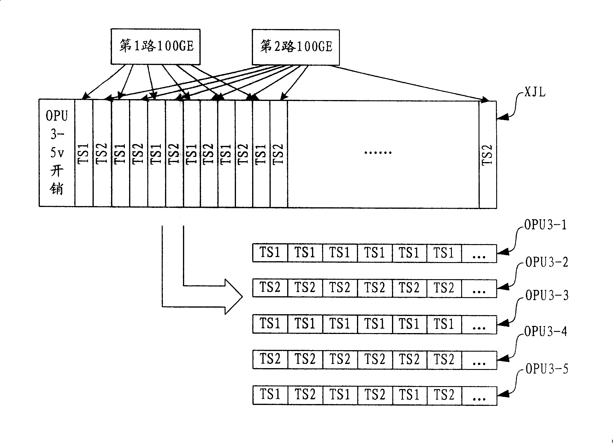
[0027] In the embodiment of the present invention, an Ethernet signal such as a 100GE signal is mapped to an adaptation protocol frame such as a GFP frame, a link access procedure (Link Access Procedure, hereinafter referred to as LAPS) protocol frame or an advanced data link control (High level Data L Control, hereinafter referred to as HDLC) protocol frame etc.; then the adaptation protocol frame is mapped to the time slot unit of the virtual concatenation group formed by more than two OPUk; finally the optical channel in the virtual concatenation group of the adaptation protocol frame will be mapped The payload unit (OPUk) is mapped to the optical channel transport unit OTUk at the same rate, that is, if k=1, OPU1 is mapped to OTU1; if k=2, OPU2 is mapped to OTU2; if k=3, OPU3 is mapped to OTU3 ; And, before the adaptation protocol frame is mapped to the time slot unit, the virtual concatenation group is divided into time slot units adapted to the Ethernet signal, after the ...


PUM


Abstract

The invention relates to a method, device and system for transmitting Ethernet signals in an optical transport network. The method includes: mapping the Ethernet signals to a time slot unit divided by a virtual concatenation group which is made up of a plurality of optical channel pure-load unit; mapping the Ethernet signals to the optical channel pure-load unit and then being mapped to the optical channel transport unit and output to the optical transport network to transmit, thus realizing the transparent transmission of the Ethernet signals in the optical transport network. The device includes a first adaptation protocol frame mapping module, a first virtual concatenation module, and a first line terminal module, which convert the Ethernet signals to the optical channel transport unit. The device includes a second line terminal module, a second virtual concatenation module and a second adaptation protocol frame mapping module. The optical channel transport unit is reduced to the Ethernet signals. The system may include the first adaptation protocol frame mapping module, the second adaptation protocol frame mapping module, the first virtual concatenation module, the second virtual concatenation module, the first line terminal module, and the second line terminal module, which convert the Ethernet signals to the OTUs and vice versa.

Description

technical field [0001] The invention relates to an optical transmission network signal transmission technology, in particular to a method, device and system for realizing the transmission of Ethernet signals in the optical transmission network. Background technique [0002] Synchronous Digital Hierarchy (SDH) uses time-division multiplexing technology to provide time-division multiplexing transmission channels with fixed bandwidth. However, with the rapid development of data communication, the suddenness and unpredictability of data services make the currently applied SDH technology less and less suitable for explosive data services. [0003] In order to meet the above requirements, the International Telecommunication Union Telecommunication Standardization Sector (ITU-T) combined the technical advantages of SDH with the bandwidth expansion technology of Dense Wavelength Division Multiplexing (DWDM), and formulated a series of standards for Optical Transport Network (OTN). ...

Claims


Application Information

Patent Timeline
IPC IPC(8): H04J14/00H04Q11/00H04L29/06
CPCH04J3/1658H04J14/0246H04J14/0252H04J14/0227H04J14/0247H04J14/025H04J14/02H04J2203/0085H04J14/0273
Inventor 陈铭吴秋游
Owner HUAWEI TECH CO LTD
Why Eureka
Try Eureka