
Programmable gain amplifier

A programming gain and amplifier technology, which is applied in the direction of gain control, amplification control, electrical components, etc., can solve the problems of influence and amplifier bandwidth change, and achieve the effect of keeping the bandwidth constant, bandwidth stable, and simple structure

Inactive Publication Date: 2008-08-13
EAST CHINA NORMAL UNIV
View PDF0 Cites 9 Cited by
  • Summary
  • Abstract
  • Description
  • Claims
  • Application Information

AI Technical Summary

Problems solved by technology

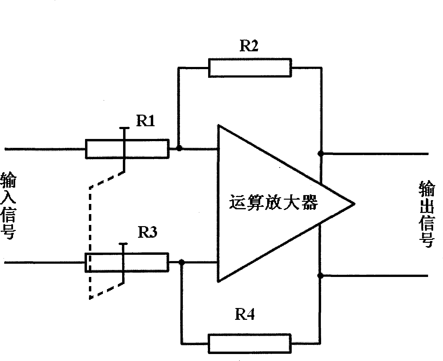
But there are also the following disadvantages: if the feedback resistors R2 and R4 are variable numerically, it will affect the poles of the input and output nodes, and the bandwidth of the amplifier will change; Load effect, it is necessary to add a buffer circuit between the front stage and the input resistors R1 and R3 to isolate

Method used


Image

  • Programmable gain amplifier
  • Programmable gain amplifier
  • Programmable gain amplifier

Examples


Embodiment 1

[0019] One of Embodiment 1 Programmable Gain Amplifier

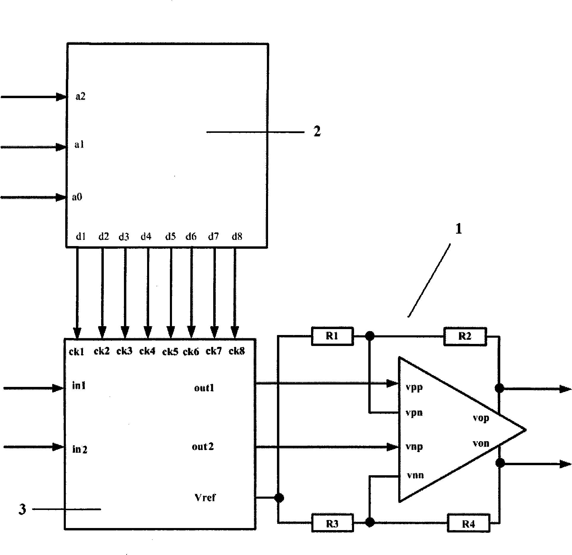
[0020] Fully balanced differential amplifier module 1 adopts the fully balanced differential amplifier (FBDDA) proposed by Hussain Alzaher and Mohammed Ismail in the article [1] in June 2001

[0021] The resistance value of the first resistor R1=1kΩ, the resistance value of the second resistor R2=10kΩ, Gmax=20log(10kΩ / 1kΩ)db=20db;

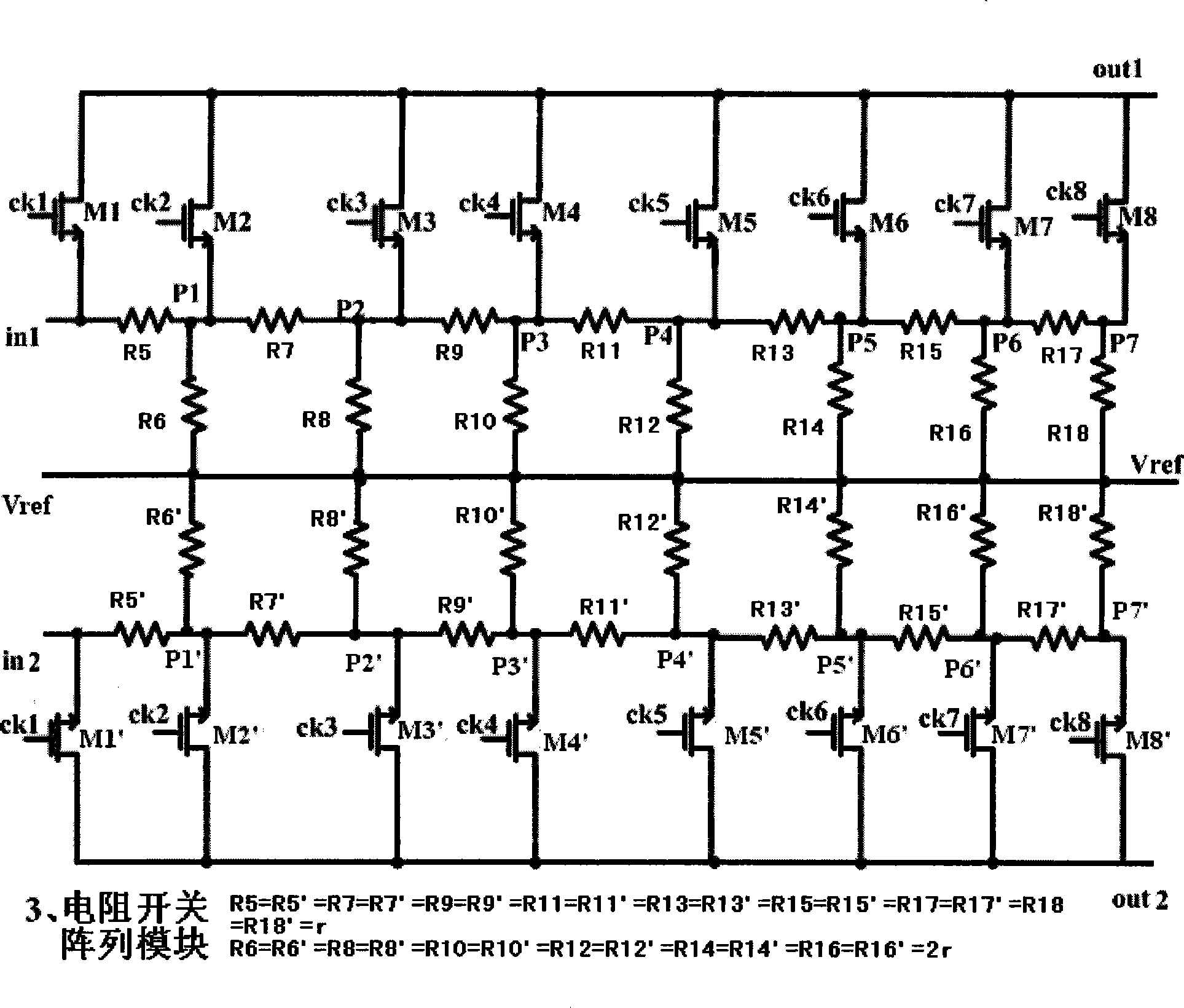
[0022] r=5kΩ, the input resistance of two symmetrical resistance attenuation networks containing analog switches is constant, which is 10kΩ;

[0023] Gmin=Gmax+maximum attenuation rate of two symmetrical resistive attenuation networks containing analog switches=20db-42db=-22db.

[0024] working principle:

[0025] When inputting the three digital signals of the third digital signal input terminal a2, the second digital signal input terminal a1, and the first digital signal input terminal a0: a2a1a0=(000) 2 When , the first digital signal output terminal d1 of the decoder module 2 outputs a...

Embodiment 2

[0028] Embodiment 2 Programmable Gain Amplifier 2

[0029] Except for the following differences, all the others are identical to Example 1.

[0030] The resistance value of the second resistor R2=32kΩ, Gmax=20log(32kΩ / 1kΩ)db=30db;

[0031] r=7.5kΩ, the input resistance of two symmetrical resistance attenuation networks containing analog switches is constant, which is 15kΩ;

[0032] Gmin=Gmax+maximum attenuation rate of two symmetrical resistive attenuation networks containing analog switches=30db-42db=-12db.

Embodiment 3

[0033] Embodiment 3 Programmable Gain Amplifier 3

[0034] Except for the following differences, all the others are identical to Example 1.

[0035] The resistance value of the second resistor R2=125kΩ, Gmax=20log(125kΩ / 1kΩ)db=42db;

[0036] r=10kΩ, the input resistance of two symmetrical resistance attenuation networks containing analog switches is constant, which is 20kΩ;

[0037] Gmin=Gmax+maximum attenuation rate of two symmetrical resistive attenuation networks containing analog switches=42db−42db=0db.


PUM

PropertyMeasurementUnit
Resistanceaaaaaaaaaa

Abstract

A programmable gain amplifier is provided, belonging to the technique field of amplifying circuit, comprising a full balanced differential amplifier module, a decoder module and a resistance switch array module. The maximum gain of the amplifier is determined by resistance ratio of inverse feedback resistive divider; attenuation of input signal is attenuated by the resistance switch array module controlled by the decoding result of the decoder module, to accomplish gain programmable property of the amplifier. The resistance switch array model is two symmetrical resistance attenuation networks comprising analog switch. The input resistance thereof is constant, to guarantee load effect constant to front stage. The amplifier has the following advantage: simple structure, stable band width, and constant input resistance. The invention forms load effect constant to front stage, so that no buffer circuit is required to separate the amplifier to the front stage.

Description

technical field [0001] The invention relates to a programmable gain amplifier, to be precise, to a programmable gain amplifier controlled by a digital signal, and belongs to the technical field of amplifying circuits. Background technique [0002] Analog circuits need to amplify or attenuate the signal, which is accomplished by a variable gain amplifier (VGA). A variable gain amplifier is an amplifier whose gain can be varied. It is widely used in disk reading drive circuits, magnetic data storage systems, electromagnetic meters, TV tuners, etc., and also plays a vital role in the analog front end of transceivers for wireless communications. [0003] With the development of digital-analog hybrid circuits, more and more variable gain amplifiers use digital signals to control gain changes (also known as programmable gain amplifiers). Compared with the analog automatic gain controller loop, the numerical control method is easy to implement, has high control precision and save...

Claims


Application Information

Patent Timeline
IPC IPC(8): H03G3/00H03G1/04
Inventor 李萌陈磊张润曦赖宗声崔建明谢传文吴岳婷陈元盈郭兴龙
Owner EAST CHINA NORMAL UNIV
Learn More