Eureka AIR delivers breakthrough ideas for toughest innovation challenges, trusted by R&D personnel around the world.

Chip testing classifier

A chip testing and sorting machine technology, applied in the direction of semiconductor/solid-state device testing/measurement, etc., can solve problems such as defects and reduce test quality

Inactive Publication Date: 2008-08-13
HON TECH INC
View PDF0 Cites 10 Cited by
  • Summary
  • Abstract
  • Description
  • Claims
  • Application Information

AI Technical Summary

Problems solved by technology

[0002] In the general semiconductor manufacturing process, a large number of chips are planned on the wafer. After the wafer is manufactured, in order to ensure the yield rate of the wafer and avoid the cost waste of the subsequent packaging process, before performing the chip cutting operation, Wafer needle testing will be carried out to test whether the electrical properties of each chip on the wafer are damaged. The wafer needle testing is to place the entire wafer on the fixture of a probe card tester. The probe card testing machine is provided with a probe card connected to the tester above the jig, the probe card has a plurality of probes, the probes of the probe card are used to detect the divided chips on the wafer, and the test The data is sent to the tester, and the tester judges whether the tested chip is a good product or a defective product. If it is a defective product, it will mark the chip or the database to filter out the defective chips first. After the wafer test operation is completed, Then put the tested wafer into the wafer box and transfer it to the next wafer cutting workstation to cut the wafer into multiple chips. Picking and storing on each tray for temporary storage or preparation for packaging operations; however, the above-mentioned operation process does not carry out separate tests for each single chip after cutting. When the chip is damaged due to a little carelessness, the operation process will not be able to reliably pick out the defective products, which will cause defects in the test operation and reduce the test quality.

Method used


Image

  • Chip testing classifier
  • Chip testing classifier
  • Chip testing classifier

Examples


Embodiment Construction

[0021] In order to further understand the present invention, now give a preferred embodiment and cooperate with the drawings, as follows in detail:

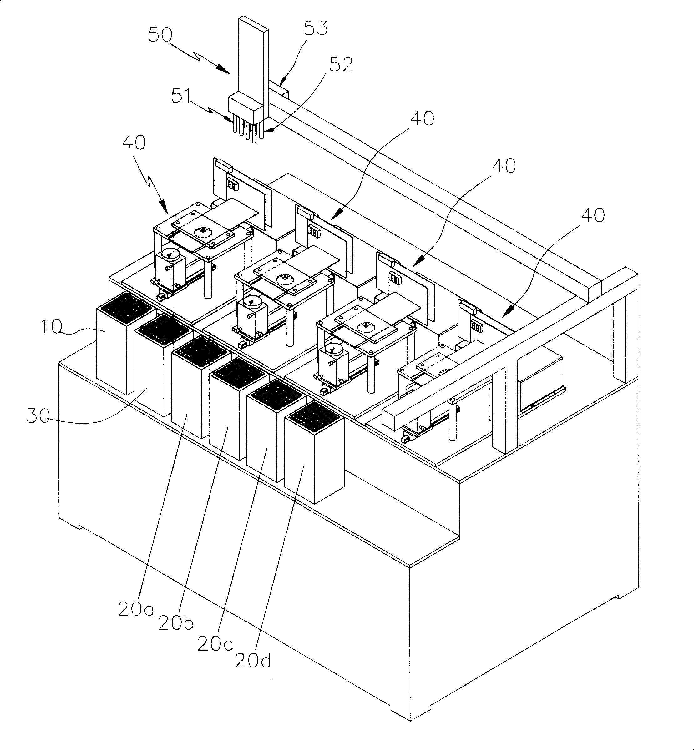
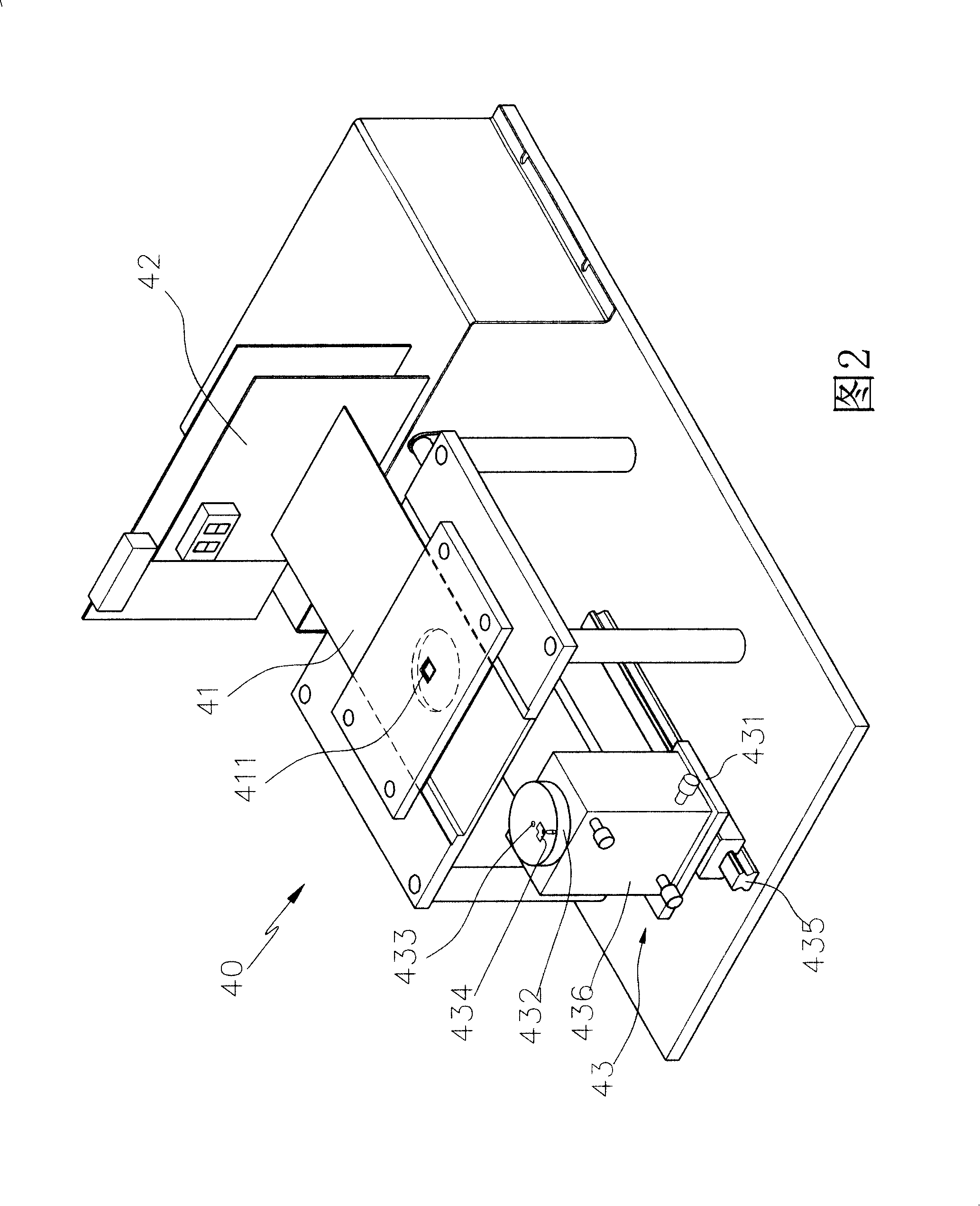
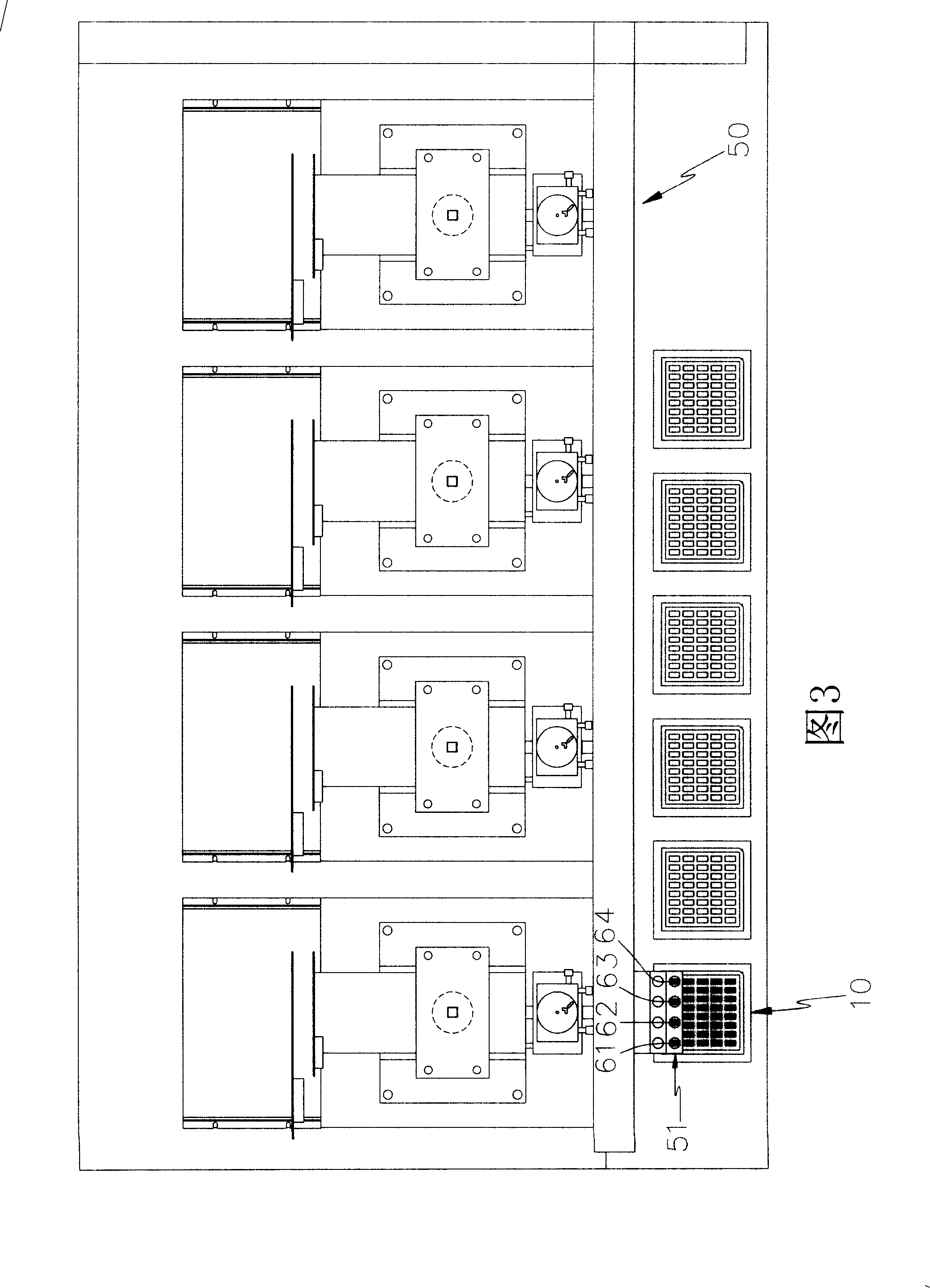
[0022] see figure 1 , shown in Fig. 2, described chip test classifier is to be provided with feeding box 10, receiving box 20a, 20b, 20c, 20d and empty box 30 at the front end of machine platform, wherein, described feeding box 10 is to hold Set at least one tray containing the chips to be tested, which can drive the tray up and down for retrieving materials, and the receiving box can be subdivided into different levels of receiving boxes 20a, 20b, 20c, 20d, each receiving box 20a, 20b, 20c, and 20d are used to store different grades of chips that have been tested. The empty box 30 can receive the empty trays used up by the supply box 10, and stack the empty trays by lifting and shifting them. It can also be used as needed. Lift and shift the received empty trays for replenishment in the receiving boxes 20a, 20b, 20c, and 20d fo...


PUM


Abstract

A chip detecting sorter comprises a feeding box arranged in the front terminal of the sorter table, holding box and an empty box. The feeding box can hold the chip to be tested to support the material. The holding box can hold the test-finished chip to take the material. The empty box can receive the empty tray at the feeding box position or supply the empty tray necessarty for the holding box. A plurality testing devices including testers, probe cards and locating tools are arranged at the rear terminal of the sorter table to test the chip. A transfer loading device is arranged among the feeding box, the holding box and the tester to transfer and load the test-finished chips and automatically transfer and load among the feeding box, holding box and the empty box and supply the empty tray. Thus, the invention can test the chips after cutting and sort immediately based on the test result so as to ensure the test quality and effectively promote the operation convenience and the usage benefit of the capacity.

Description

technical field [0001] The invention relates to a chip testing and sorting machine capable of consistently and automatically performing chip testing and sorting operations, thereby effectively improving operation convenience and testing productivity. Background technique [0002] In the general semiconductor manufacturing process, a large number of chips are planned on the wafer. After the wafer is manufactured, in order to ensure the yield rate of the wafer and avoid the cost waste of the subsequent packaging process, before performing the chip cutting operation, Wafer needle testing will be carried out to test whether the electrical properties of each chip on the wafer are damaged. The wafer needle testing is to place the entire wafer on the fixture of a probe card tester. The probe card testing machine is provided with a probe card connected to the tester above the jig, the probe card has a plurality of probes, the probes of the probe card are used to detect the divided c...

Claims


Application Information

Patent Timeline
IPC IPC(8): H01L21/66
Inventor 谢旼达游庆祥
Owner HON TECH INC
Why Eureka
Eureka Blog
Learn More