
Real time frequency measurement method based on amplitude linear change model

A linear change, frequency measurement technology, applied in the direction of frequency measurement device, etc., can solve the problem of affecting the frequency measurement accuracy, inappropriate system slight oscillation and no oscillation.

Active Publication Date: 2010-09-15
STATE GRID JIANGSU ELECTRIC POWER CO ELECTRIC POWER RES INST +1
View PDF0 Cites 0 Cited by
  • Summary
  • Abstract
  • Description
  • Claims
  • Application Information

AI Technical Summary

Problems solved by technology

Method 1: Xu Qingqiang, Suonan Jiale, Song Guobing, Shi Jinghui, Ge Yaozhong's "Real-time Measurement of Instantaneous Frequency of Power System During Oscillation" ("Chinese Journal of Electrical Engineering", 2003, 23(1): 51-54+69), and Method 2: Qing-qiang Xu, Jiale Suonan, and Yao-zhong "Ge. Real-time Measurement of Mean Frequency in Two-machine System During Power Swings" ("IEEE Trans. on Power Delivery", 2004, 19(3): 1018- 1023) is suitable for severe system oscillations, but not for slight system oscillations and no oscillations; Chen Zhaohui, Huang Shaofeng, Yang Qixun "Real-time Measurement of Power System Oscillation Frequency Based on Synthetic Phasor" ("Power System Automation" 2004, 28 (4): 32-35) Use the integrated phasor to obtain the system frequency, which is suitable for the situation of slight oscillation and no oscillation of the system, and the oscillation frequency of the system can be obtained at the same time, but the asymmetry of the three-phase current caused by any reason will directly affect Measurement accuracy to frequency

Method used


Image

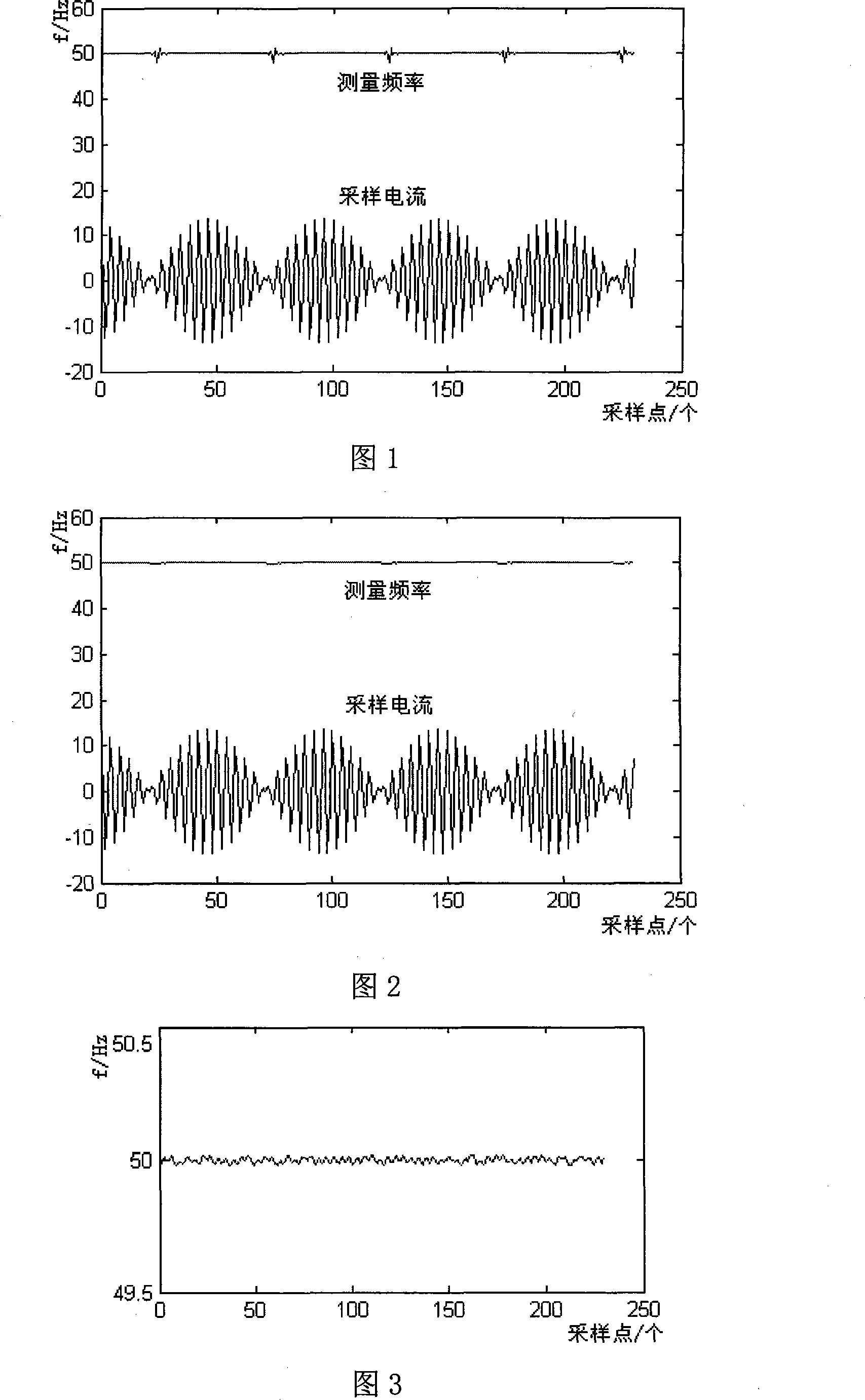
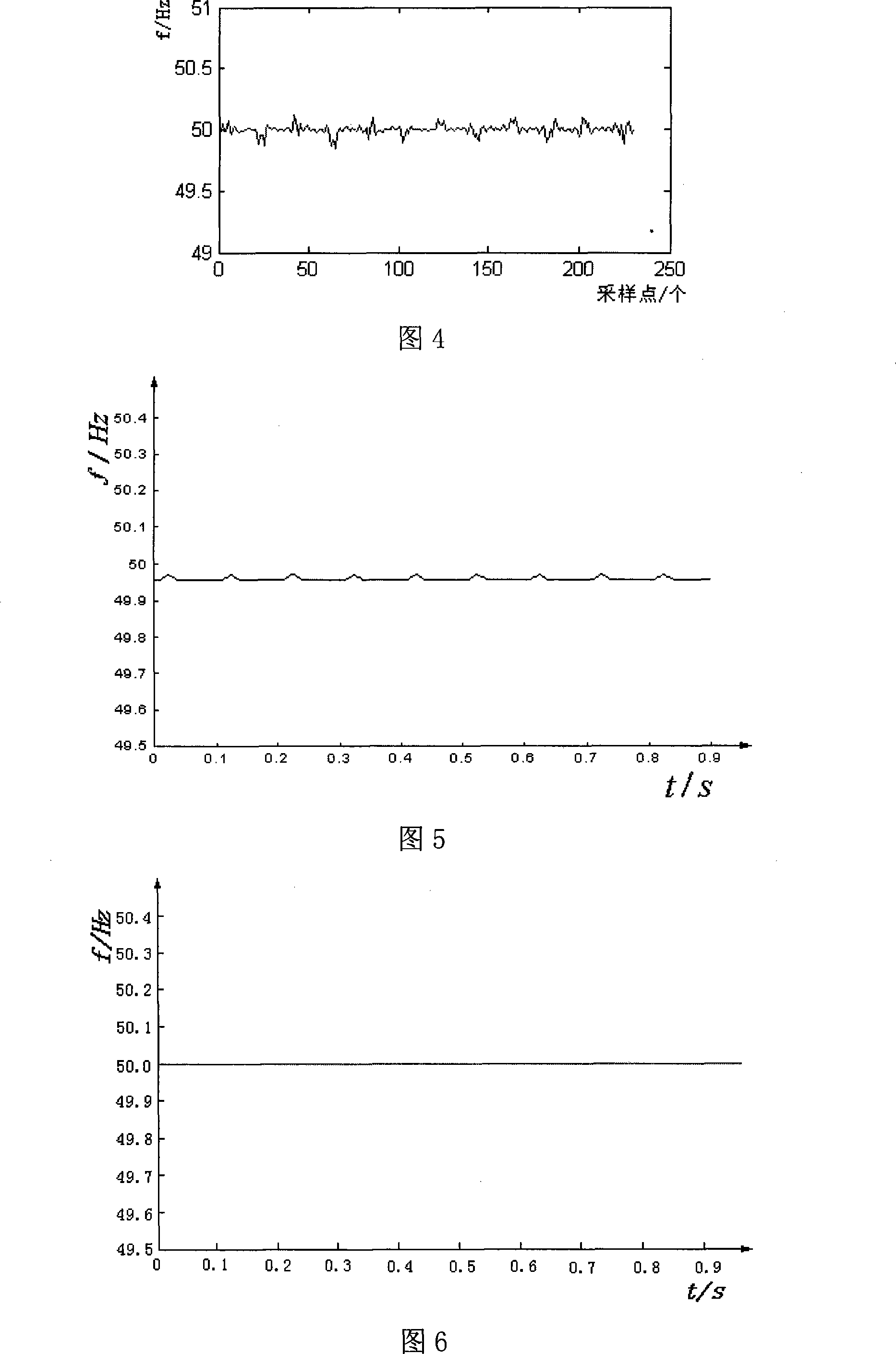
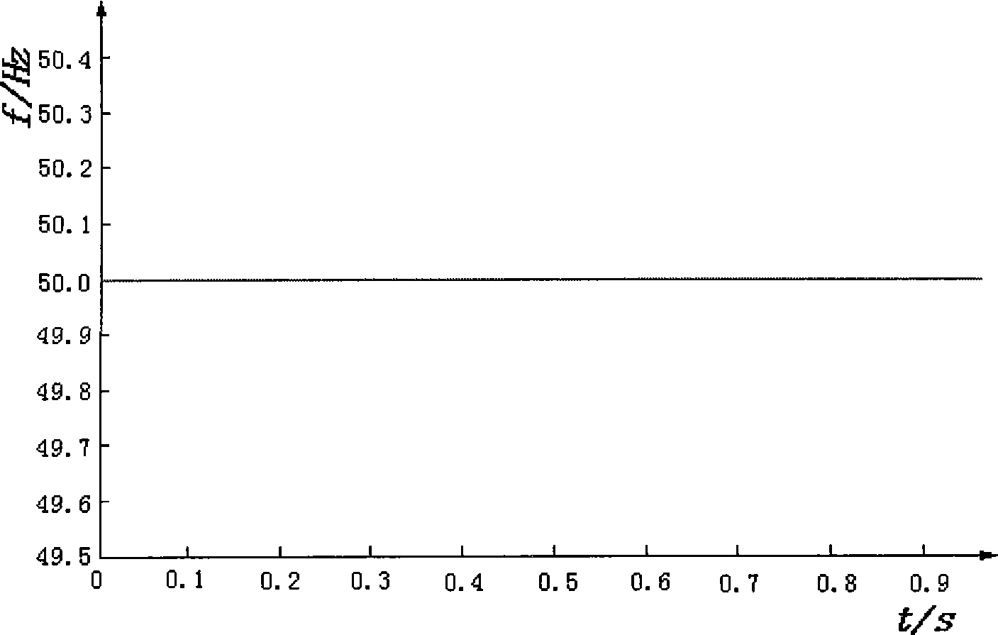
  • Real time frequency measurement method based on amplitude linear change model
  • Real time frequency measurement method based on amplitude linear change model
  • Real time frequency measurement method based on amplitude linear change model

Examples


Embodiment

[0115] The embodiment of frequency measurement method of the present invention is as follows:

[0116] (1) Get the current sampling value

[0117] Sampling at 4 points per power frequency cycle, any phase current sampling value is i k i k-1 i k-2 i k-3 ..., where i k is the current sampling point, i k-1 i k-2 i k-3 …is the previous sampling point.

[0118] (2) Calculation of x value

[0119] Calculate the value of x as x = Σ j = 1 5 [ ( i k - j i k - j - 1 - i ...


PUM


Abstract

The present invention relates to a method for measuring real time frequency based on amplitude linear variation model which is characterized of including: gaining real time frequency of f=arc cos(x) / (2piT) through mathematical derivation based on the amplitude linear variation corresponding current sampling point in short time; analyzing infection of frequency by sampling data in different sampling time interval and determining sampling time interval; setting threshold of denominator to eliminate error of measuring frequency caused by too small of denominator; calculating inverse cosine function of real time frequency by Talor series method to gain measuring frequency. In the formula: f is real time frequency, x is result calculated by current sampling value, T is sampling time interval. The present invention has merits of simple implement, rapid speed of measuring frequency, high precision and wide application scope, can provide exactly real time state variate for system without digital filtering technique.

Description

technical field [0001] The present invention relates to a power system parameter measurement method, in particular to a real-time frequency measurement method based on an amplitude linear variation model for accurately measuring the real-time frequency of a power system, providing real-time state variables for the system, and used for low-frequency load shedding devices, synchrophasor measuring devices and relay protection devices, etc. It belongs to the technical field of power system automation. Background technique [0002] Frequency is the main performance parameter of power system. There have been many large-scale power outages caused by frequency collapse in the world. Insufficient power of the power system will cause the frequency to drop, and the automatic power generation system will start the rotating equipment to restore the frequency of the power system to normal. When the frequency is seriously insufficient, the low-frequency load shedding device cuts off part...

Claims


Application Information

Patent Timeline
Patent Type & Authority Patents(China)
IPC IPC(8): G01R23/02
Inventor 许庆强许扬
Owner STATE GRID JIANGSU ELECTRIC POWER CO ELECTRIC POWER RES INST
Learn More