
RF transmitter with compensation of differential path delay

A transmitter and relative delay technology, applied in the parts, electrical components, amplifiers and other directions of the amplifying device, which can solve the problems of chip area and extravagant power consumption.

Inactive Publication Date: 2008-07-30
AMPLEON NETHERLANDS
View PDF2 Cites 14 Cited by
  • Summary
  • Abstract
  • Description
  • Claims
  • Application Information

AI Technical Summary

Problems solved by technology

While this has the advantage of measuring the magnitude of the problem, at source, it has the luxury of die area as well as power consumption, which negates the use of polar modulation or envelope tracking for efficiency gains

Method used


Image

  • RF transmitter with compensation of differential path delay
  • RF transmitter with compensation of differential path delay
  • RF transmitter with compensation of differential path delay

Examples


Embodiment Construction

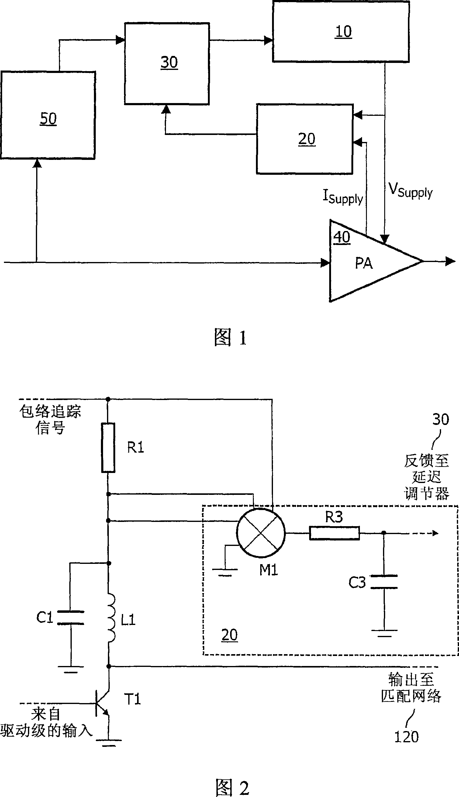
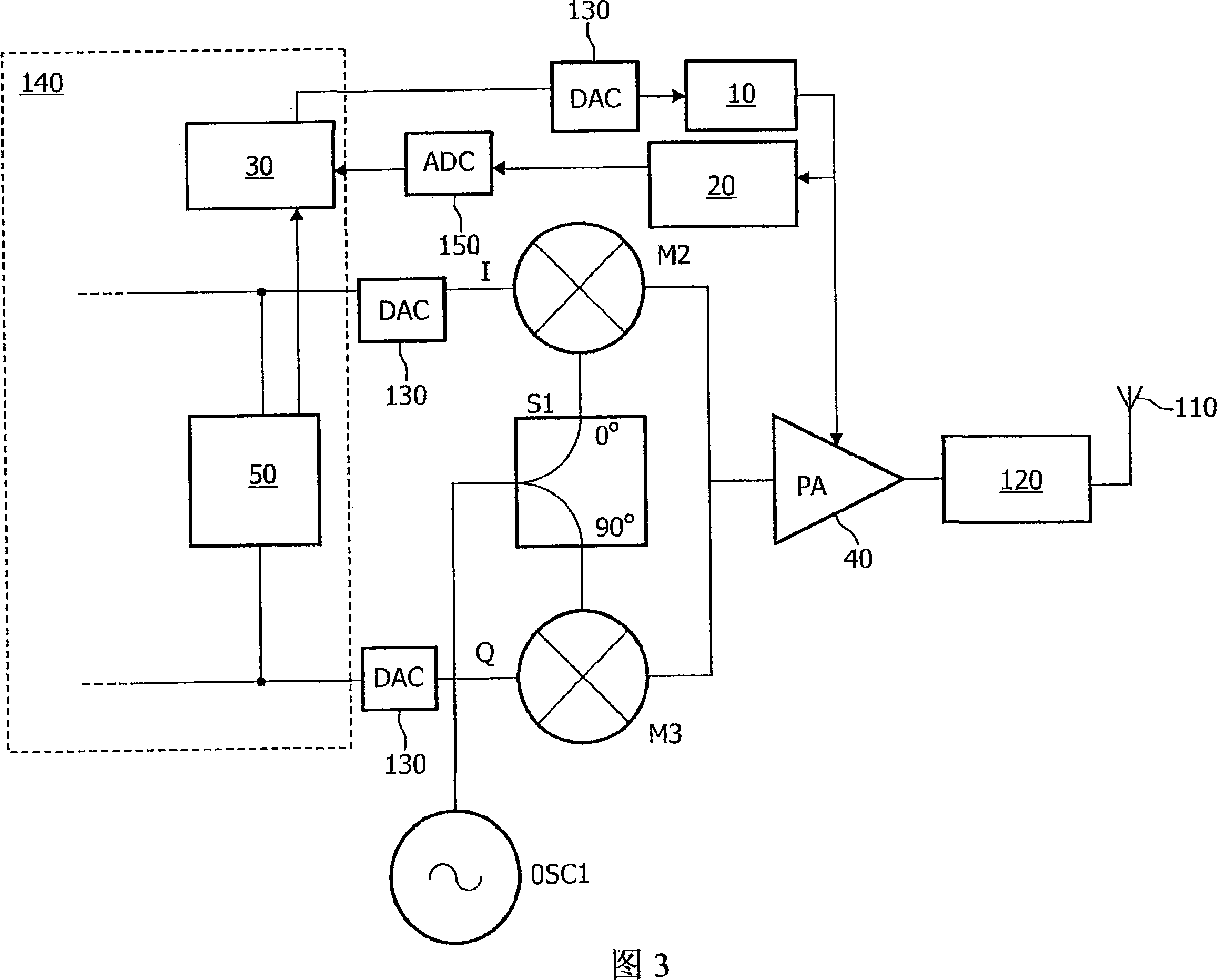
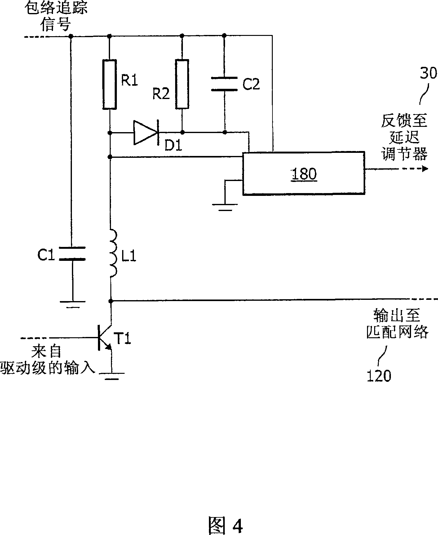
[0020] The described embodiment provides means for detecting the existence of any delay between the main signal channel and the channel carrying the envelope of the fully modulated signal without down-converting the output signal. For envelope tracking, this is possible because the power amplifier is driven by a fully modulated signal, rather than a constant envelope signal that contains only the phase component of the fully modulated signal. Similarly, this embodiment can be extended to polarization modulation, as long as some modulation is performed in the amplified signal (such as a small part of the envelope of the driving signal). In principle, it is possible to specifically generate voltage modulation and current modulation to detect the delay, instead of using the amplitude modulation obtained from the information content of the transmitted signal to detect the delay. As long as the relative delay can be measured, and the desired output spectrum is not excessively polluted,...


PUM


Abstract

A transmitter has a power amplifier (40) to amplify an input signal having amplitude modulation, a supply voltage controller (10) to control a supply voltage of the power amplifier (40) according to the envelope, a sensor (R1) for sensing a modulation of a current drawn by the power amplifier (40), a delay detector (20) for detecting a delay of the controlled supply voltage relative to the sensed current, and a delay adjuster (30) for compensating the relative delay according to the detected delay. By sensing a current drawn, the delay detected can include any delay contributed by the power amplifier (40) up to that point, and yet avoid the more complex circuitry needed to derive the delay from an output of the power amplifier. Thus the distortion and out of band emissions caused by differential delays can be reduced more effectively.

Description

Technical field [0001] The present invention relates to a transmitter, an integrated circuit, and a device having the integrated circuit, and a method of operating such a transmitter. Background technique [0002] The constant envelope modulation scheme has traditionally been widely used in radio communication systems. This is because the constant envelope modulation scheme allows the transmitter to use a saturated power amplifier, providing high efficiency and long battery life. However, in consideration of improved spectrum efficiency, radio communication systems are increasingly inclined to use non-constant envelope modulation schemes. According to the usual point of view, this requires the use of linear power amplifiers, resulting in reduced efficiency and shortened battery life. Since this is not attractive, people use more advanced transmitter architectures to make up for these shortcomings. Polarization modulation may be the most famous of these schemes, but envelope track...

Claims


Application Information

Patent Timeline
Patent Type & Authority Applications(China)
IPC IPC(8): H03F1/02
CPCH03F1/0205H03F1/0227H03F1/32H03F3/24H03F2200/102H03F2200/336H03F2200/462H03F2200/504H03F2200/99H04B1/04
Inventor 布赖恩·J·明尼斯保罗·A·穆尔
Owner AMPLEON NETHERLANDS
Learn More