Multipoint and object touch panel arrangement as well as multipoint touch orientation method
A multi-point touch screen and touch screen technology, which is applied to projection devices, printing devices, camera bodies, etc., can solve the problems of incorrect position reporting, difficulty in touch panel manufacturing process, high complexity of calculation circuits, and difficulty in reporting positions, etc.
- Summary
- Abstract
- Description
- Claims
- Application Information
AI Technical Summary
Problems solved by technology
Method used
Image
Examples
Embodiment 1
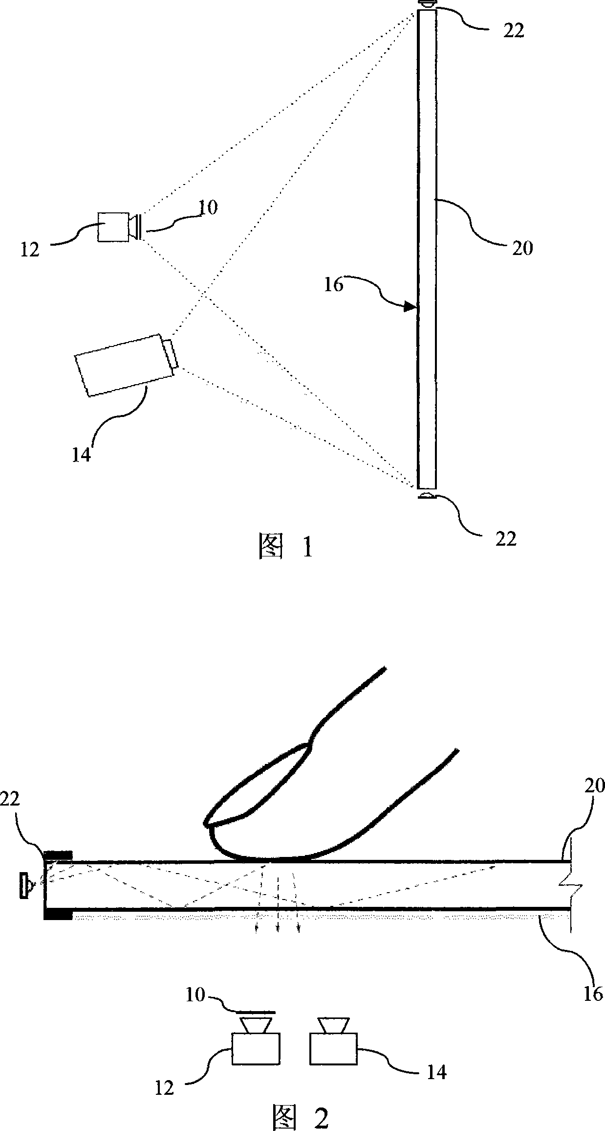
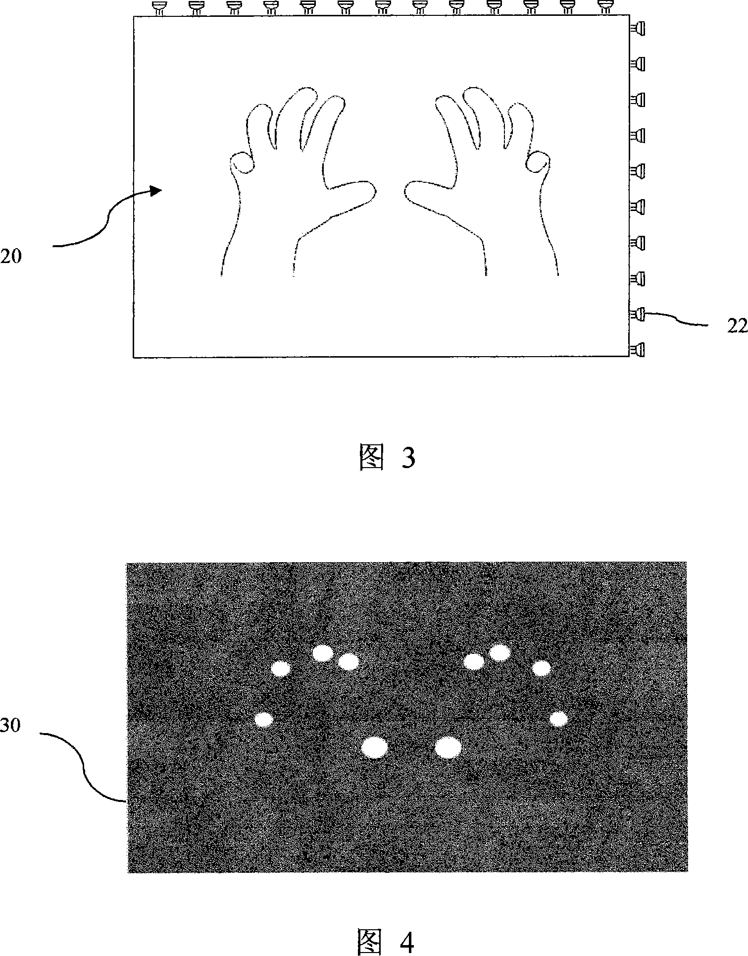
[0104] Example 1. FIG. 1 is a schematic structural diagram of an embodiment of a multi-touch screen device of the present invention. The device includes: a touch screen 20 made of a highly transparent acrylic glass plate, and the four sides of the touch screen 20 are polished; a plurality of LEDs 22 that provide infrared light with a wavelength of 850nm; When an object touches the panel of the touch screen 20, the total reflection at the touch point is destroyed, and the infrared rays are scattered here to generate infrared imaging. A projection soft curtain 16 for displaying images is attached to the back of the acrylic glass plate 20, and the soft curtain 16 has good infrared transmission performance. The infrared camera 12 captures infrared reflection images presented on the acrylic plate 20 . The camera 12 is provided with an optical filter 10 corresponding to the wavelength of the infrared light emitted by the LED 22 and is 850nm light wave in front of the taking lens o...
Embodiment 2
[0109] Embodiment 2, referring to Fig. 13 . The difference between this embodiment and Embodiment 1 is that it also includes a layer of transparent and elastic silica gel 40, which is coated on the front of the touch panel 20, and the silica gel and the touch panel form a single total reflection layer; The projection soft screen 16 has the properties of being breathable and can block infrared rays from the outside, and it is placed on the above-mentioned silica gel layer 16 . Because the back side of the soft curtain 16 is rough, there will be an air layer between the silica gel film and the projection screen. Adhering to the silica gel layer 40, and because the silica gel layer 40 has a strong adsorption capacity, the air will be squeezed out from between the soft curtain 16 and the silica gel layer 40, thus destroying the total reflection and producing bright spots. When the pressure disappears, due to the elasticity of the silica gel layer 40, it will immediately return to...
Embodiment 3
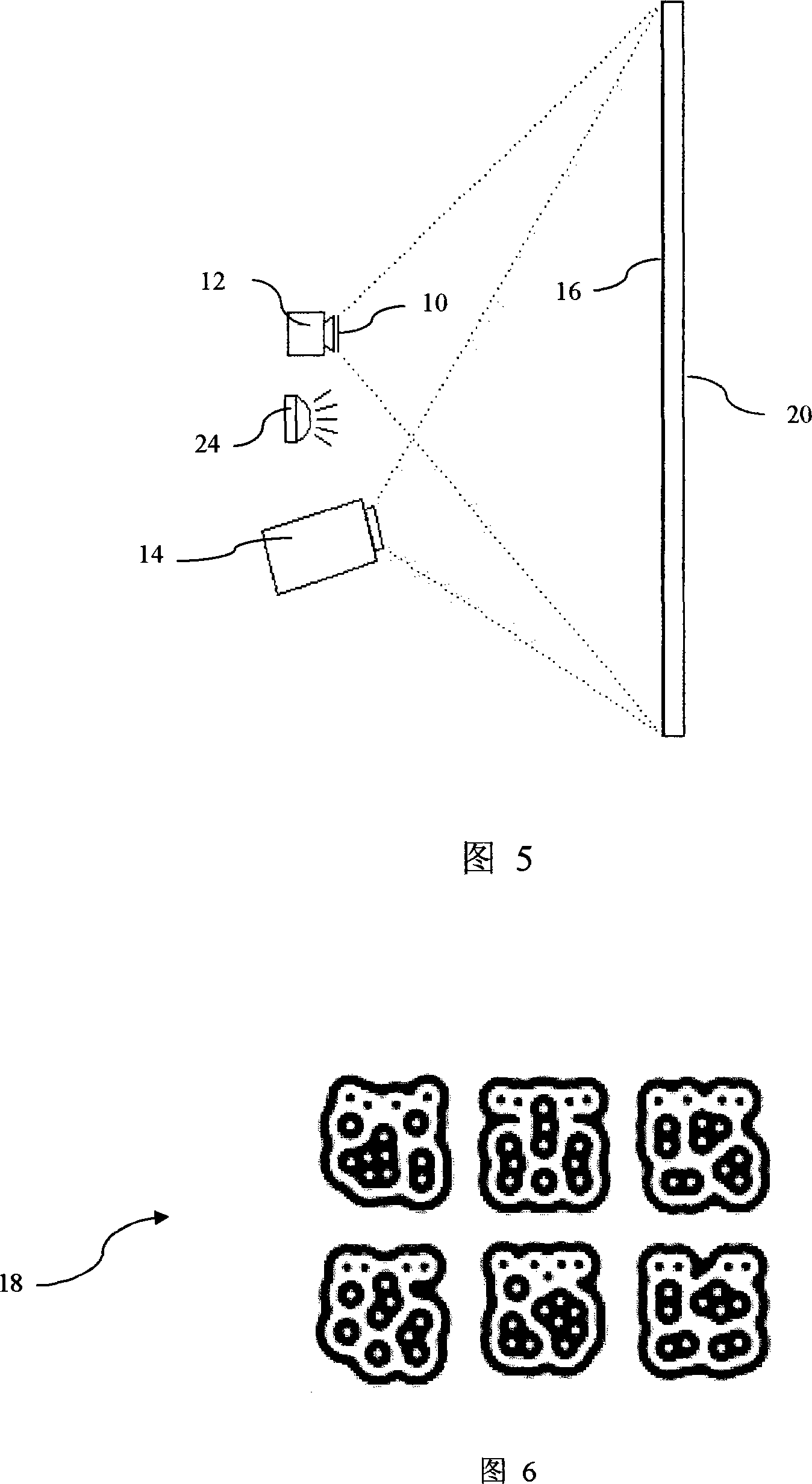
[0110] Embodiment 3, see Fig. 5. The difference between this embodiment and Embodiment 1 is that the LED device providing infrared light is arranged on the back of the touch panel 20, and the infrared camera captures the reflected image of the infrared light from objects on the front of the touch screen.
[0111] The device in Embodiment 3 can identify the shape of the reflective infrared imaging pattern label attached to the touch object on the touch screen 20, that is, the sample of the infrared reflective imaging of the label that can be collected in advance, and match and compare it with the currently acquired reflective imaging of the touching object. To confirm what kind of touching object, as well as the coordinates and angle of the object, whether it is in motion and the direction of motion. and perform corresponding actions.
[0112] The infrared light source of the device in embodiment 3 is from the infrared emitting device 24 placed behind the acrylic glass plate 2...
PUM
 Abstract
Description
Claims
Application Information
 - R&D
- Intellectual Property
- Life Sciences
- Materials
- Tech Scout
- Unparalleled Data Quality
- Higher Quality Content
- 60% Fewer Hallucinations
Browse by: Latest US Patents, China's latest patents, Technical Efficacy Thesaurus, Application Domain, Technology Topic, Popular Technical Reports.
© 2025 PatSnap. All rights reserved.Legal|Privacy policy|Modern Slavery Act Transparency Statement|Sitemap|About US| Contact US: help@patsnap.com


