Eureka AIR delivers breakthrough ideas for toughest innovation challenges, trusted by R&D personnel around the world.

Synchronous powder feeder for laser reproduction

A technology of laser remanufacturing and synchronous powder feeding, applied in the field of powder conveying device, can solve the problems of intermittent transmission mechanism, uneven powder feeding rate, powder blocking, etc. adaptable effect

Inactive Publication Date: 2008-07-30
ZHEJIANG UNIV OF TECH
View PDF0 Cites 7 Cited by
  • Summary
  • Abstract
  • Description
  • Claims
  • Application Information

AI Technical Summary

Problems solved by technology

If the air flow is not used, the powder feeding rate will be uneven, and the powder will not be well gathered at the laser spot, and it is particularly easy to cause powder blockage at the powder feeding nozzle.
If it is transported by air flow, it is easy to cause powder agglomeration and powder blockage, and the transmission mechanism of the powder feeder is also prone to phenomena such as intermittent and stuck powder feeding due to the shaft rotary motion pair
Chinese patent 0224563.5 discloses a laser coating powder feeder, which uses the hub type powder feeding wheel to send the powder falling from the powder storage hopper on one side to the powder outlet on the other side. The disadvantage of this device is: the hub type powder feeding The bearing connecting the wheel and the housing is prone to intermittent and stuck due to powder ingress

Method used


Image

  • Synchronous powder feeder for laser reproduction

Examples


Embodiment Construction

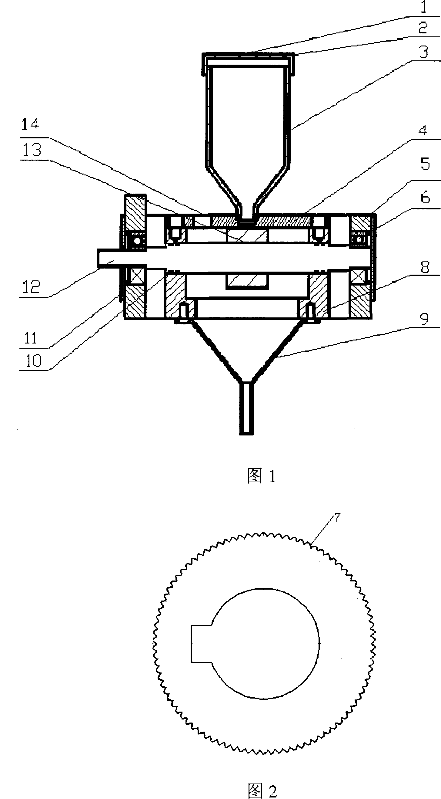
[0012] The present invention will be further described below in conjunction with the accompanying drawings.

[0013] See Figure 1-2: a synchronous powder feeder for laser remanufacturing, including a casing 5, which is equipped with a core 8, a powder storage bin 3 connected to the core 8 is installed above the casing 5, and a powder storage bin 3 connected to the core 8 is installed below the casing 5. The powder outlet funnel 9, the rotating shaft 12 runs through the inner core 8 and is installed on the shell 5 through the rolling bearing 6, the rotating shaft 12 is connected with the stepper motor through a coupling, and the rotating shaft 12 located in the inner core 8 is keyed with a powder feeding roller Wheel 13, the upper end of the powder feeding roller 13 corresponds to the outlet of the powder storage bin 3, the lower end of the powder feeding roller 13 corresponds to the entrance of the powder outlet funnel 9, and the circumferential surface of the powder feeding ro...


PUM


Abstract

The invention relates to a synchronous powder feeder used for reproducing the laser and comprises an outer shell. An inner core is arranged inside the outer shell. A powder-storing chamber communicated with the inner core is arranged at the upper part of the outer shell and a powder-outlet device communicated with the inner core is arranged at the lower part of the outer shell. A rotating shaft passes through the inner core and is arranged on the outer shell through a bearing and the rotating shaft is connected with a drive electric motor. The upper key of the rotating shaft positioned in the inner core is connected with a powder-feeding roller, the upper end of the powder-feeding roller corresponds to the outlet of the powder-storing chamber, the lower end of the powder-storing chamber corresponds to the inlet of the powder-storing chamber and grooves for holding the powder are evenly distributed on the circumferential surface of the powder-feeding roller. An air vent, which communicates the inner core and the atmosphere, is arranged on the outer shell. The invention has the advantages that: firstly, the operation is stable and reliable and the phenomenon of the shaft gyration kinematic pair of the drive mechanism being interrupted and jammed fails to occur; and secondly, the powder feeding is continuous, even and controllable and a strong adaptability of the powder granularity is available.

Description

(1) Technical field [0001] The invention relates to a powder conveying device in the field of laser remanufacturing. (2) Technical background [0002] At present, as a new material processing method, laser remanufacturing is widely used in various fields of industrial manufacturing. There are two main automatic delivery methods for laser remanufacturing materials: powder feeding type and wire feeding type. The existing domestic powder feeding devices, such as scraper type, volumetric screw type and other powder feeders, have strict conditions for powder size and dry humidity due to their design. If the air flow is not used, the powder feeding rate will be uneven, and the powder will not be well gathered at the laser spot, and it is particularly easy to cause powder blockage at the powder feeding nozzle. If the air flow is used to convey, it is easy to cause powder agglomeration and powder blocking, and the transmission mechanism of the powder feeder is also prone to phenom...

Claims


Application Information

Patent Timeline
IPC IPC(8): C23C24/10
Inventor 姚建华陈智君
Owner ZHEJIANG UNIV OF TECH
Why Eureka
Eureka Blog
Learn More