Motor and control unit thereof

A control device and electric motor technology, which is applied in the direction of AC motor control, motor generator control, electronic commutation motor control, etc., can solve the problems of large eddy current loss, large eddy current of electromagnetic steel plate, and high cost of control devices, so as to reduce cost, performance-enhancing effect

Inactive Publication Date: 2008-07-23
DENSO CORP
View PDF2 Cites 7 Cited by
  • Summary
  • Abstract
  • Description
  • Claims
  • Application Information

AI Technical Summary

Problems solved by technology

[0009] Regarding the problem of the soft magnetic body used in the motor, the existing motor technology is based on the premise that the electromagnetic steel sheet is laminated in the direction of the rotor axis. In order to solve the many problems of the above-mentioned motor, if it becomes The structure in which the magnetic flux increases and decreases in the three-dimensional direction causes a large eddy current in the electromagnetic steel sheet, and there is a problem that a large eddy current loss occurs
[0010] Regarding the problem of the motor control device, especially in the case of a small-capacity motor, the number of electronic components is large. Compared with the drive of a DC motor, There is a problem that the cost of the control device becomes high

Method used


Image

  • Motor and control unit thereof
  • Motor and control unit thereof
  • Motor and control unit thereof

Examples


Embodiment Construction

[0127] Hereinafter, a motor to which various embodiments of the present invention are applied will be described in detail with reference to the drawings.

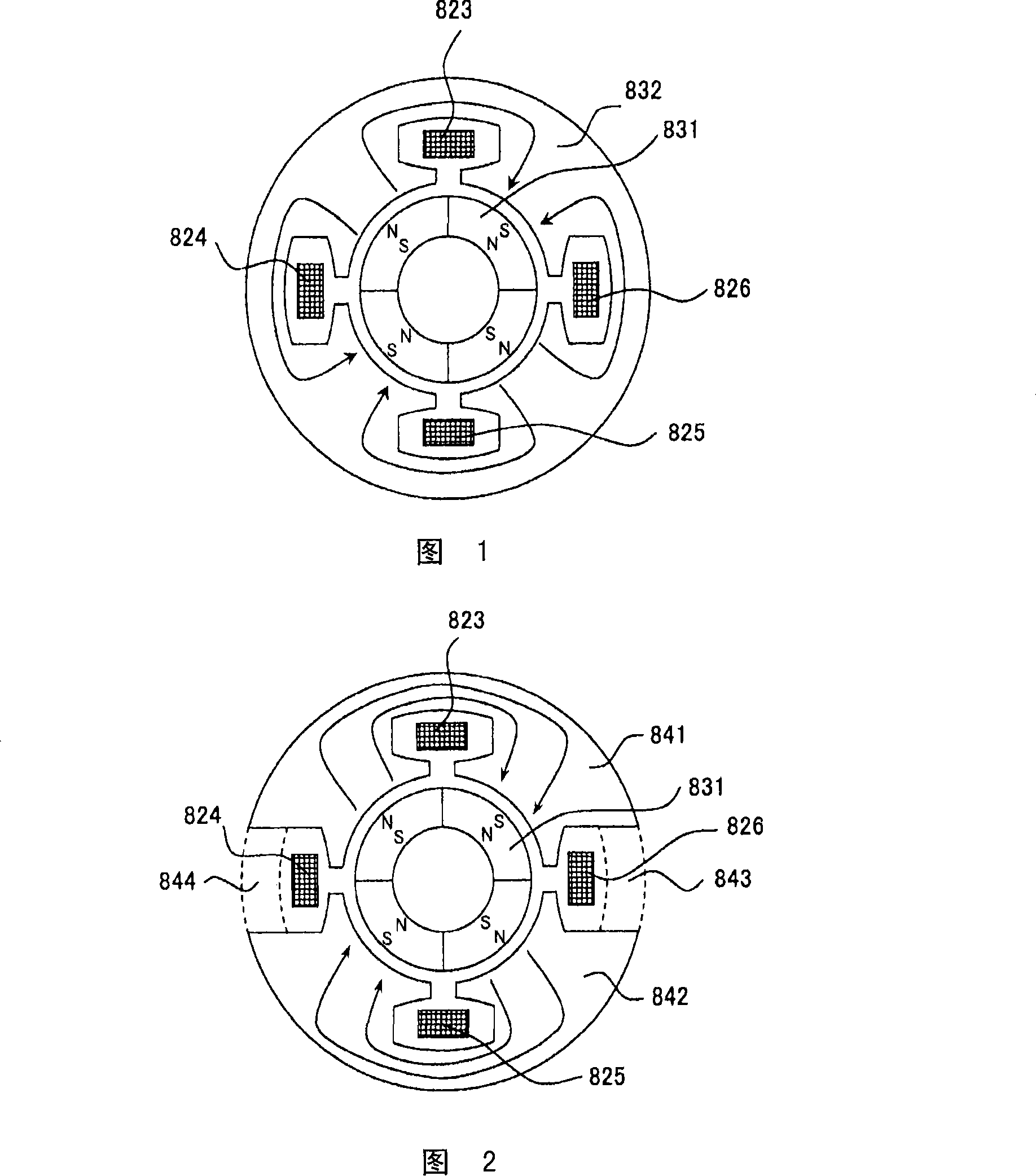
[0128] Figure 1 shows a single-phase AC, 4-pole motor. 831 is a permanent magnet of the rotor, 832 is a stator core made of soft magnetic material, and 823, 824, 825, and 826 are single-phase windings. There are several methods for winding the windings. One example is winding single-phase windings with windings 823 and 824 and single-phase windings with windings 825 and 826 . At this time, the amount of the maximum magnetic flux interlinked with the winding 823 shown in FIG. 1 is 1 / 2 of the magnetic flux of one magnetic pole of the permanent magnet 831 .

[0129] Next, FIG. 2 shows the motor in which the parts 843 and 844 shown in the wavy line part are cut out and removed from the motor of FIG. 1 . At this time, the amount of the maximum magnetic flux interlinked with the winding 823 shown in FIG. 2 is the magnetic flux ...


PUM


Abstract

A composite motor includes: a rotor of at least for polarities in which N pole and S pole are alternately arranged in the circumferential direction; a stator core having stator magnetic circuits which are magnetically separated in a range of 360 degrees of electrical angle; and (N-1) sets of winding of an N-phase motor (N is a positive integer). The composite motor is configured so that the current in the windings effectively functions on the magnetic circuits.

Description

technical field [0001] The present invention relates to an electric motor mounted on an automobile, a truck, or the like, and a control device thereof. Background technique [0002] Conventionally, a brushless motor in which coils of respective phases are concentratedly wound around stator magnetic poles is known (for example, refer to Patent Document 1). FIG. 95 is a longitudinal cross-sectional view illustrating a schematic configuration of such a conventional brushless motor. In addition, FIG. 97 is a sectional view taken along the line AA-AA of FIG. 95 . [0003] In these figures, a brushless motor of a 4-pole 6-slot type is shown, and the winding structure of the stator is a so-called concentrated winding, and the coils of each phase are concentratedly wound on each stator magnetic pole. In addition, FIG. 96 shows the arrangement relationship of windings such as U, V, W, etc., in a state where the stator is expanded by one turn in the circumferential direction. The h...

Claims


Application Information

Patent Timeline
Patent Type & Authority Applications(China)
IPC IPC(8): H02K1/14H02K19/12H02K21/14H02K29/00H02P6/08H02K3/04H02P21/00H02P21/13H02P27/04
CPCB60L7/00B60L2210/20H02K1/141H02K1/145H02K1/148H02K19/103H02K21/145H02K21/16H02K2201/12Y02T10/64Y02T10/72H02K19/12
Inventor 梨木政行
Owner DENSO CORP
Why Eureka
Try Eureka