Double coil variable current control circuit of vacuum circuit breaker permanent magnet mechanism

A vacuum circuit breaker and permanent magnet mechanism technology, which is applied to high-voltage air circuit breakers, circuits, high-voltage/high-current switches, etc., can solve the problem of increased dispersion of opening and closing time, inability to meet synchronous closing, and inability to overcome current Excessively large and other problems, to achieve the effect of increasing the opening action current, reducing the time, and avoiding sudden changes in force characteristics

Inactive Publication Date: 2011-06-01
XI AN JIAOTONG UNIV +1
View PDF0 Cites 0 Cited by
  • Summary
  • Abstract
  • Description
  • Claims
  • Application Information

AI Technical Summary

Problems solved by technology

High-voltage circuit breakers require faster action speeds. Under the condition of a certain number of ampere-turns, in order to properly reduce the current, the number of turns can only be increased. The more turns of the coil, the greater the inductance, and the current rises to the action requirement. The longer the current time, the longer the action time will be, which will increase the dispersion of opening and closing time, and cannot meet the requirements of synchronous closing
[0005] The existing mechanism design generally focuses on the rationality of the structure, so that the characteristics of the permanent magnet mechanism can be well matched with the characteristics of the vacuum circuit breaker. The defect of insufficient sub-speed

Method used


Image

  • Double coil variable current control circuit of vacuum circuit breaker permanent magnet mechanism
  • Double coil variable current control circuit of vacuum circuit breaker permanent magnet mechanism
  • Double coil variable current control circuit of vacuum circuit breaker permanent magnet mechanism

Examples


Embodiment Construction

[0026] The present invention will be further described in detail below in conjunction with the accompanying drawings.

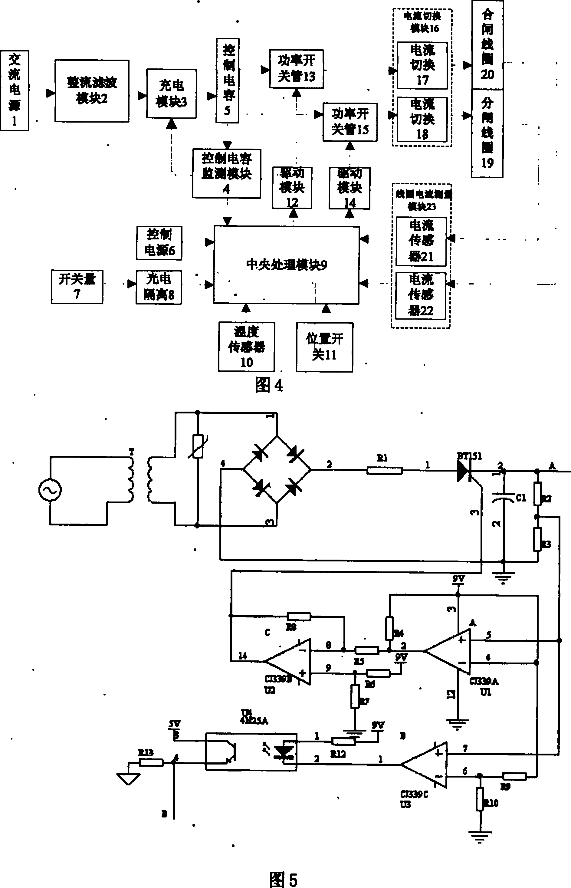
[0027]Referring to FIG. 4 , the present invention includes a rectifier filter module 2 connected to the AC power supply 1 , the output end of the rectifier filter module 2 is connected to the current input end of the charging module 3 , and the output end of the charging module 3 is connected to the input end of the control capacitor 5 . The voltage feedback end of the control capacitor 5 is connected with the input end of the control capacitance detection module 4, the signal output end of the capacitance detection module 4 is connected with the signal input end of the charging module 3, and the other output end of the capacitance detection module 4 It is connected with the signal input terminal of the central processing module 9 for monitoring the state of the control capacitor detection module 4, and the current output terminal of the control capacitor 5 is...


PUM


Abstract

The invention provides a double coil variable current control circuit for vacuum circuit breaker permanent magnet mechanism; in the closing process, an opening coil is negatively electrified, which partially neutralizes the permanent magnet holding force, reduces the closing motion current, simultaneously regulates the current in the closing coil and lowers the kinetic energy and the impact speedof the iron core on the premise of ensuring the closing speed; in the opening process, the opening coil is positively electrified, the closing coil is negatively electrified or the opening coil is positively electrified, the closing coil is positively electrified; the voltages and currents in the opening coil and the closing coil are sampled by the coil current measuring module, and the collecteddata are fed back to a central control module which can calculate the current change rates of the present coils and regulate the current value in the opening coil based on the result; by feeding backsamplings of the voltages and currents in the opening coil and the closing coil of the permanent magnet mechanism, the invention can regulate the current amplitude in coils and makes a reasonable fitbetween the operating characteristics of the permanent magnet mechanism and the counterforce characteristics of the circuit breaker.

Description

technical field [0001] The invention belongs to the field of electronic applications, in particular to a dual-coil variable current control circuit of a permanent magnet mechanism of a vacuum circuit breaker. Background technique [0002] Bistable permanent magnet mechanism is a new type of operating mechanism designed for vacuum circuit breakers. It has attracted wide attention due to its high reliability and small dispersion of opening and closing times, and is widely used in medium voltage fields. Its main action features are: when the opening or closing signal is sent, the power supply supplies power to the opening coil or closing coil, and the electromagnetic force generated by the coil overcomes the reaction force and the permanent magnet holding force, drives the iron core and then drives the circuit breaker contact. Complete the opening and closing operations. When the action is completed, the permanent magnet provides a holding force to keep the contacts in a close...

Claims


Application Information

Patent Timeline
Patent Type & Authority Patents(China)
IPC IPC(8): H01H33/38H01H33/59H01H3/28H01F7/18
Inventor 耿英三王振兴王建华姚建军刘志远
Owner XI AN JIAOTONG UNIV
Why Eureka
Try Eureka