Magnetic latching relay

A magnetic latching relay, relay technology, applied in the direction of electromagnetic relays, relays, electromagnetic relay details, etc., can solve the problem of reducing the electrical life of the relay contacts and the ability to withstand short-term current impact, the relay contact bounce time is large, affecting the relay. Reliability and other issues, to achieve the effect of improving the resistance to short-term current impact, ensuring consistency and stability, and uniform and soft elasticity

Active Publication Date: 2014-09-10
EVE ENERGY CO LTD
View PDF6 Cites 9 Cited by
  • Summary
  • Abstract
  • Description
  • Claims
  • Application Information

AI Technical Summary

Problems solved by technology

Since the contact bounce occurs during the circuit connection process, and the power grid short circuit or most circuit loads (such as inductive loads, capacitive loads, incandescent lamp loads, etc.) have a large impact current when they are connected, so the contact bounce The phenomenon will cause great harm to the contacts, thus affecting the reliability of the relay. At the same time, when the contacts bounce back, the high-frequency pulse formed by the circuit being on and off is still a harmful interference signal to the surrounding electronic devices.
[0005] The traditional shrapnel design, whether it is a non-bending straight piece or a shrapnel bending type, due to the influence of the contact position and contact size, the elastic design of the shrapnel has certain limitations, which leads to the bounce time of the relay contact. Too large, greatly reducing the electrical life of the relay contacts and the ability to withstand short-term current shocks

Method used


Image

  • Magnetic latching relay
  • Magnetic latching relay
  • Magnetic latching relay

Examples


Embodiment Construction

[0048] The technical solutions of the present invention will be further described below in conjunction with the accompanying drawings and through specific implementation methods.

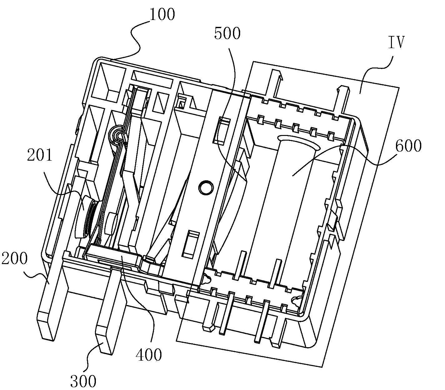
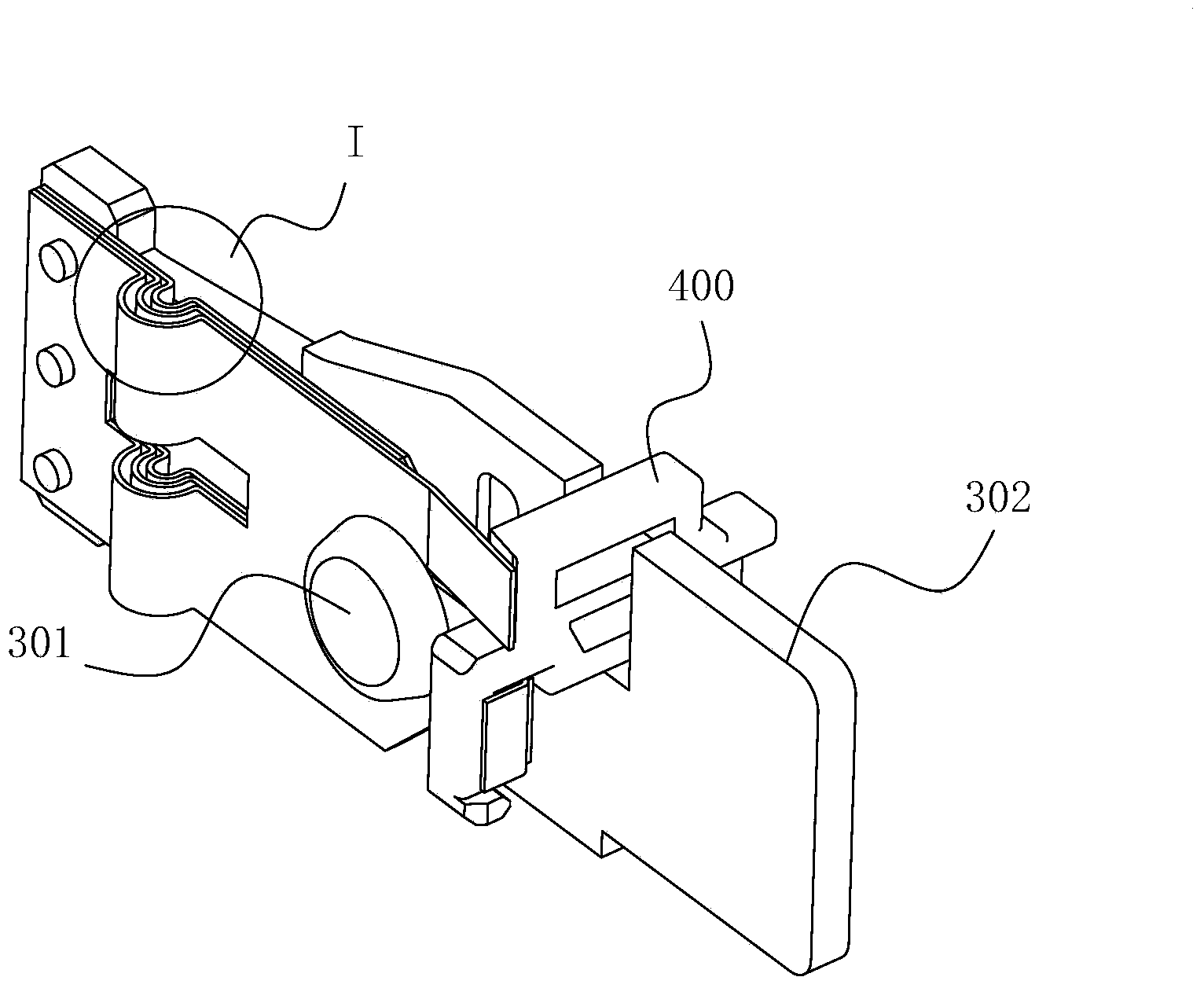
[0049] Such as Figure 1-8 As shown, in this embodiment, a magnetic latching relay according to the present invention includes a relay housing 100, and inside the relay housing 100, a static plate assembly 200 and a moving reed assembly corresponding to the static plate assembly 200 are arranged. 300, the static contact 201 is set on the static piece assembly 200, and the moving contact 301 is set on the moving reed assembly 300. The electrical equipment supplies power, and when the movable contact 301 is separated from the static contact 201, the relay forms an open circuit and the electrical equipment is powered off. The moving reed assembly 300 is connected with the push card 400 and is driven to move by the push card 400 , the push card 400 is driven by the armature assembly 500 , and the movem...


PUM


Abstract

The invention discloses a magnetic latching relay. The magnetic latching relay includes a relay shell. A static piece assembly and a dynamic reed assembly are arranged in the relay shell. The dynamic reed assembly comprises a dynamic piece and an elastic piece. One end of the elastic piece is fixed on the dynamic piece, and the other end of the elastic piece is driven by a push card and can move in the direction towards or away from the static piece assembly. The end, connected with the push card, of the elastic piece is provided with a card slot. The elastic piece is connected with the push card through the card slot. The end, making contact with the push card, of the elastic piece is of a straight piece type structure. The push card is fixed through the arranged card slot, so that the position, making contact with the elastic piece, of the push card is fixed relatively, no gap between the elastic piece and the push card exists in the process of pressing the elastic piece through the push card, the pressed position is determined and unique, it is guaranteed that the pressure is constant, and the consistency and stability of relay products are guaranteed.

Description

technical field [0001] The invention relates to the technical field of relays, in particular to a magnetic latching relay. Background technique [0002] The magnetic latching relay is a new type of relay developed in recent years, and it is also an automatic switch. Like other electromagnetic relays, it can automatically switch on and off the circuit. [0003] Magnetic latching relays need a certain contact pressure to ensure stable and reliable contact contact. The existing technology mainly bends the shrapnel first, and then mechanically compresses the bent part of the shrapnel when the product is in motion, thereby obtaining a certain shrapnel pressure. However, due to the influence of its own stress release, manufacturing process, logistics transportation, mechanical shock, etc., the shrapnel is distorted, and then the elastic force changes, which affects the consistency of the product, and even leads to no pressure on the contact, making the product completely invalid....

Claims


Application Information

Patent Timeline
Patent Type & Authority Applications(China)
IPC IPC(8): H01H51/01H01H50/64
Inventor 李开波冯朝均罗楠王世峰
Owner EVE ENERGY CO LTD
Why Eureka
Try Eureka