
Cryostat for transporting cooled equipment at a cryogenic temperature

A technology of cryostat and cooling equipment, which can be applied to machines, mechanical equipment, heat exchange equipment, etc. that use refrigerant evaporation, and can solve problems such as reducing vacuum quality.

Inactive Publication Date: 2008-07-16
SIEMENS MAGNET TECH
View PDF0 Cites 13 Cited by
  • Summary
  • Abstract
  • Description
  • Claims
  • Application Information

AI Technical Summary

Problems solved by technology

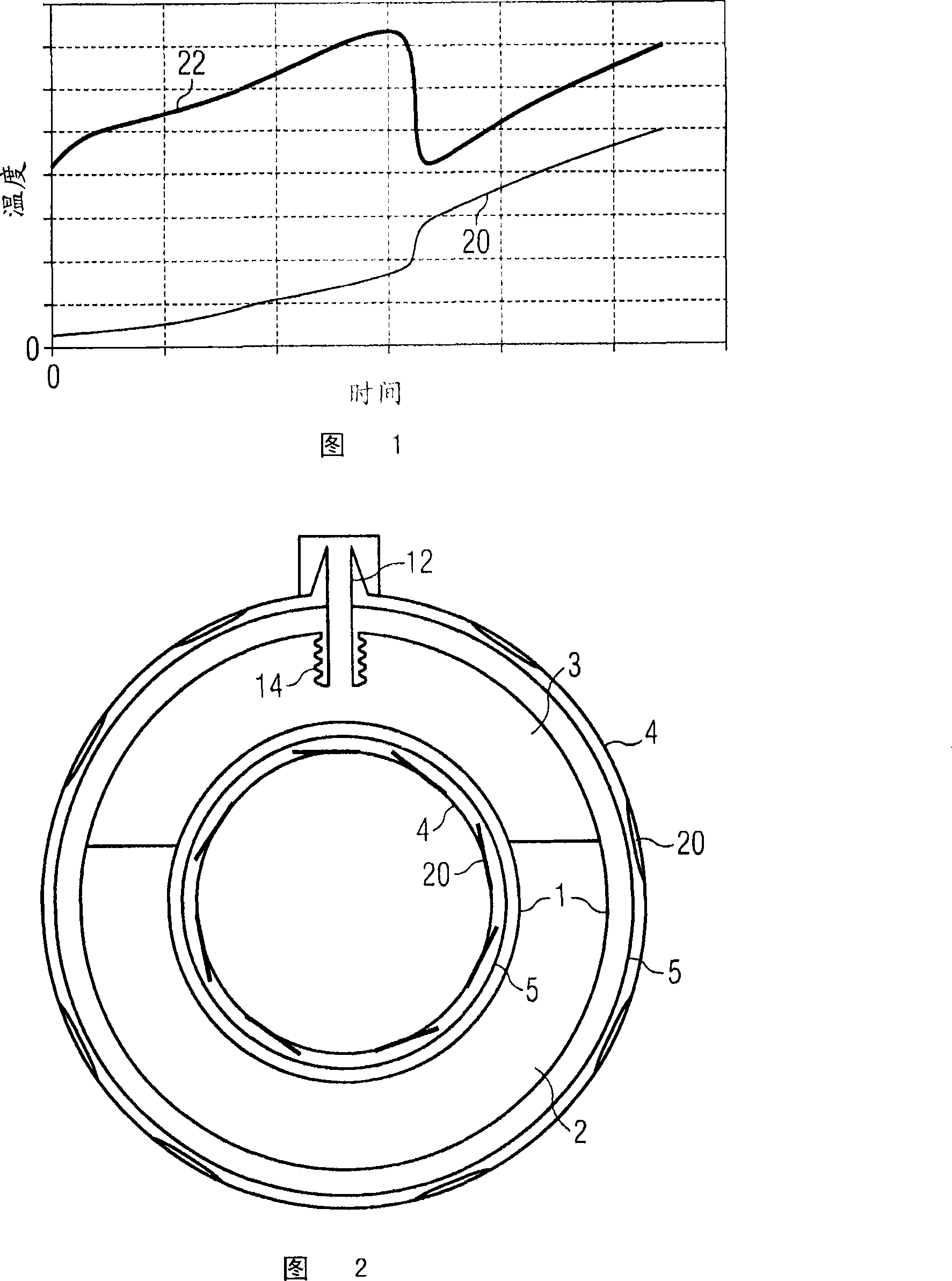
Some frozen vacuum contaminants will return to a gaseous state, reducing the quality of the vacuum

Method used


Image

  • Cryostat for transporting cooled equipment at a cryogenic temperature

Examples


Embodiment Construction

[0012] Although many known cryogenically cooled devices, such as the magnets used in magnetic resonance imaging (MRI) systems, operate at liquid helium temperatures (approximately 4K), delivering such systems at liquid helium temperatures would be difficult and expensive because Liquid helium is costly and has limited availability. Thus, the cooling device may only be provided with a limited amount of liquid helium for delivery, which may be exhausted before the cooling device reaches its destination. The cooling device may then become hot due to heat inflow, as described above.

[0013] As described above, the insulation effect of the vacuum insulation layer is reduced due to the presence of vacuum contaminants. Many of these contaminants are solid at the temperature of liquid helium, but evaporate when the device heats up. This in turn means that the heat influx into the cooling device increases rapidly at the boiling temperature of the vacuum contaminants. Typically, thi...


PUM


Abstract

A cryostat for transporting cooled equipment at an upper cryogenic temperature, the cryostat being arranged to cool the cooled equipment by a working cryogen which boils at a lower cryogenic temperature, comprising a vacuum container surrounding the cooled equipment and defining a nominally evacuated layer between the vacuum container and the cooled equipment. Means are provided to reduce contamination of the nominally evacuated layer by a vacuum contaminant which is present in gaseous form within the evacuated layer at the upper cryogenic temperature, but which is retained in liquid or solid form at the lower cryogenic temperature.

Description

technical field [0001] The invention relates to a cryostat Background technique [0002] As is known in the art, a cryogenic cooling device, such as a superconducting magnet structure for a magnetic resonance imaging (MRI) system, is typically delivered in a cryostat at least partially filled with a working cryogen. During delivery, the refrigerant boils, thereby maintaining the cooling unit at the boiling point of the operating refrigerant. [0003] During transport, the rate at which the cooling unit heats up depends on the heat flow into the unit. This is determined by three main reasons. First, radiant heat is emitted from a relatively warm surface onto adjacent surfaces of the cooler. A typical example of this is the relatively warm outer vacuum chamber radiating heat onto the cryogen vessel containing the cooling device. Second, heat can be conducted through the mechanical support structure that holds the cooling device in place, or the mechanical support structure...

Claims


Application Information

Patent Timeline
IPC IPC(8): F25B19/00
CPCY02E60/321F17C2203/0395H01F6/04F17C3/085F17C2270/0527F16L59/141F16L59/065F17C2221/012F17C2221/017F17C2270/0536Y02E60/32F17C11/005F17C13/006
Inventor A·F·阿特金斯M·J·M·克瑞普
Owner SIEMENS MAGNET TECH
Learn More