
AI-based alloy sputtering target and process for producing the same

A technology of base alloy and sputtering target, which is applied in the field of Al-base alloy sputtering target and its preparation, can solve the problems of no proposal, high production cost, troublesome preparation method and the like

Active Publication Date: 2008-07-16
KOBE STEEL LTD +1
View PDF10 Cites 4 Cited by
  • Summary
  • Abstract
  • Description
  • Claims
  • Application Information

AI Technical Summary

Problems solved by technology

[0004] However, in a method such as the above-mentioned method of inserting a barrier metal layer, there is a problem in that the preparation method becomes troublesome and thus the production cost is high
Specifically, in terms of Ni-containing Al-based alloy sputtering targets for forming thin films of Al-Ni alloys or Al-Ni-rare earth element alloys, no technique has been proposed that can overcome the problems described above. A thin film of Ni alloy or Al-Ni-rare earth element alloy can be used as an interconnection material capable of being directly connected to a conductive oxide film constituting a pixel electrode

Method used


Image

  • AI-based alloy sputtering target and process for producing the same
  • AI-based alloy sputtering target and process for producing the same
  • AI-based alloy sputtering target and process for producing the same

Examples


preparation example Construction

[0038] 3. The method for preparing an Al-based alloy sputtering target according to item 1 or 2, the method comprising:

[0039] preparing a dense body of Al-based alloy; then

[0040] forging the dense body of the Al-based alloy to obtain a slab; then

[0041] rolling the slab at a rolling temperature of 400 to 500°C, a reduction ratio of 5 to 15% per pass, and a total reduction ratio of 60 to 90%; and then

[0042] Heating is performed at a temperature in the range of 300 to 400°C for 1 to 2 hours.

[0043] 4. The method according to item 3, wherein said preparation of the dense body of the Al-based alloy comprises:

[0044] Al-based alloy preforms are prepared according to the spray forming method, and

[0045] Al-based alloy preforms are densified by means of densification.

[0046]According to the Al-based alloy sputtering target of the present invention, since the crystallographic orientation in the normal direction of the sputtering surface is appropriately controll...

Embodiment 1

[0127] From Al-based alloys whose compositions are shown in Tables 1 and 2, Al-based alloy preforms (density: substantially 50 to 60%) were obtained according to the following spray forming method.

[0128] (Injection molding conditions)

[0129] Melt temperature: 1000°C

[0130] Gas / Metal Ratio: 6Nm 3 / kg

[0131] Spray distance: 1050mm

[0132] Gas atomizer outlet angle: 7°

[0133] Collector Angle: 35°

[0134] Subsequently, each preform obtained was sealed in a capsule, followed by degassing, and then densified with a HIP apparatus. The HIP treatment was performed at a HIP temperature of 550° C. for a HIP time of 2 hours at a HIP pressure of 85 MPa.

[0135] The Al-based alloy dense body thus obtained was forged under conditions of a heating temperature of 500° C. before forging, a heating time of 2 hours, and an upsetting ratio of 10% or less each time, thereby obtaining a slab (dimensions: thickness 60 mm, width 540mm and length 540mm).

[013...


PUM

PropertyMeasurementUnit
widthaaaaaaaaaa
lengthaaaaaaaaaa

Abstract

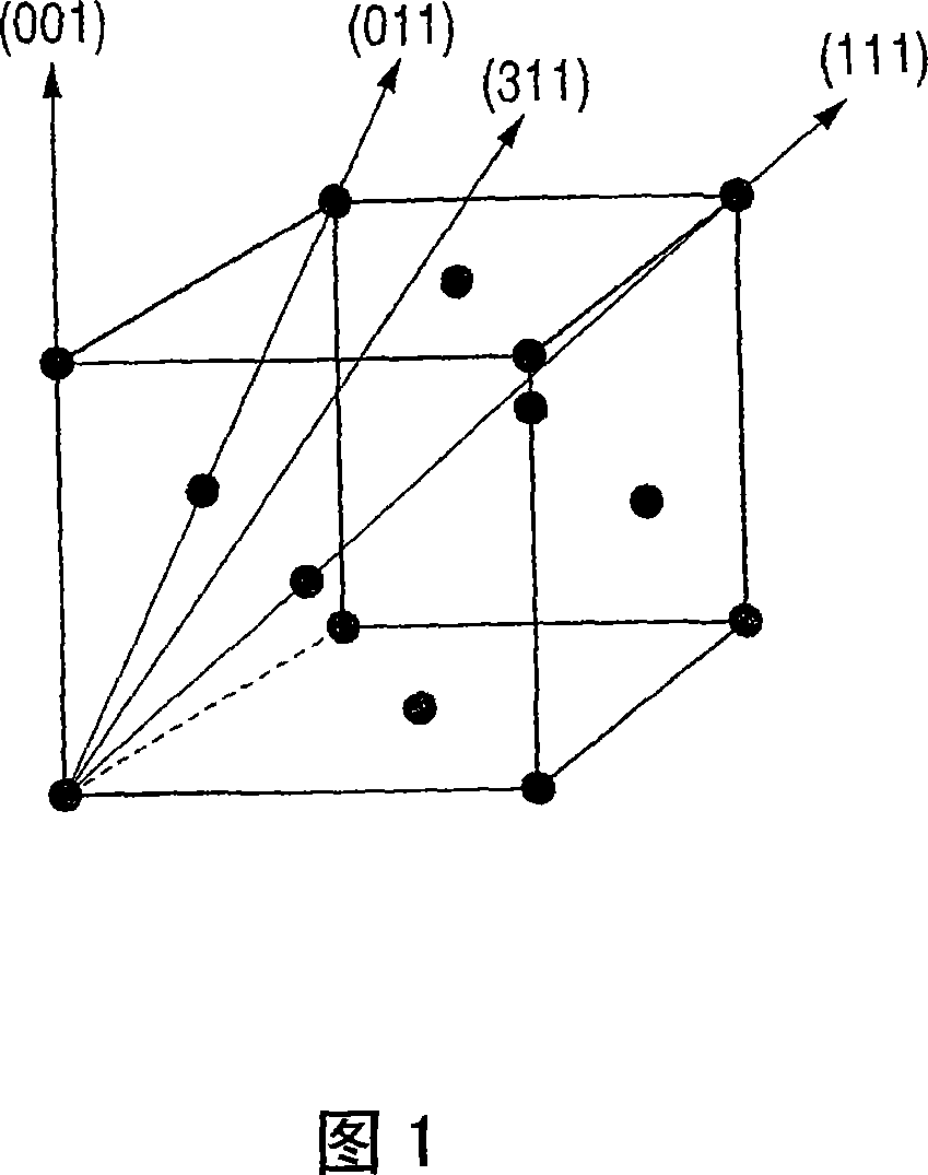
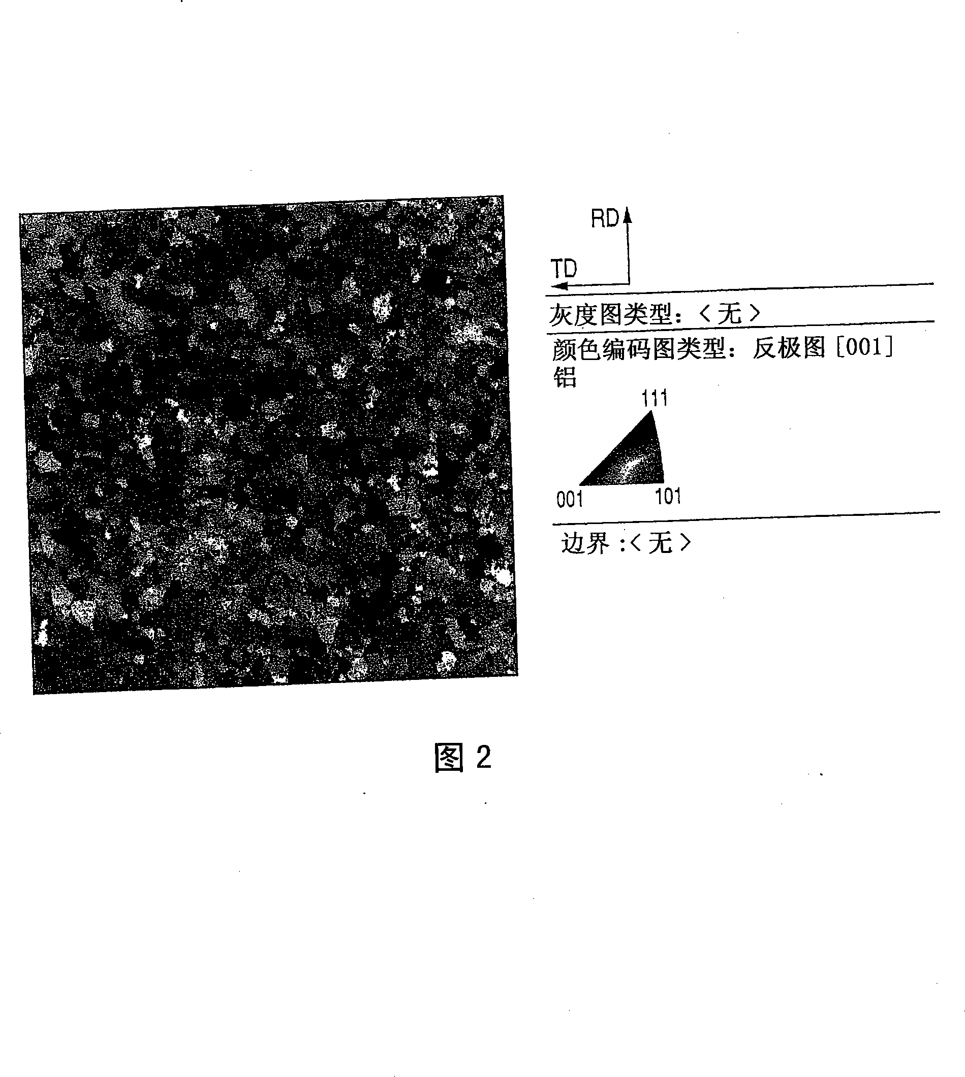
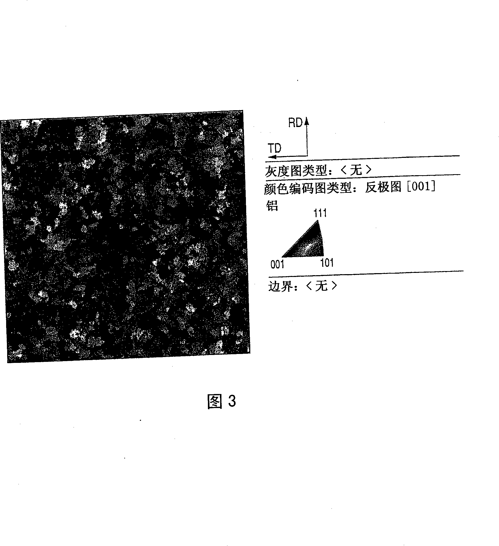
The present invention relates to an Al-based alloy sputtering target comprising Ni in an amount of 0.05 to 10 atomic %, wherein when the normal line of the sputtering surface of the Al-based alloy sputtering target is observed according to the electron backscattering diffraction pattern method When crystallographic orientations <001>, <011>, <111> and <311> in the direction, the Al-based alloy sputtering target satisfies: (1) The ratio of the P value to the total area of ​​the sputtering surface is 70% Above, where the P value represents the sum of the area fractions of <001>±15°, <011>±15°, <111>±15° and <311>±15°; (2) the area of ​​<011>±15° The fraction-to-P-value ratio is 30% or more; and (3) the area fraction-to-P-value ratio of <111>±15° is 10% or less.

Description

technical field [0001] The invention relates to an Al-based alloy sputtering target containing Ni and a preparation method thereof. In detail, it relates to a Ni-containing Al-based alloy sputtering target in which the crystallographic orientation in the direction normal to the sputtering surface is controlled. Background technique [0002] Al-based alloys with low resistivity and easy processing are widely used in flat panel displays (FPDs) such as liquid crystal displays (LCDs), plasma display panels (PDPs), electroluminescent displays (ELDs) and field emission displays (FEDs). field, and is used as a material for interconnect films, electrode films, and reflective electrode films. [0003] For example, an active matrix type liquid crystal display includes a thin film transistor (TFT) as a switching element, a pixel electrode made of a conductive oxide film, and a TFT substrate having interconnections including scanning lines and signal lines, And the scanning lines and ...

Claims


Application Information

Patent Timeline
Patent Type & Authority Applications(China)
IPC IPC(8): C23C14/34C23C14/14C22C21/00C22F1/04
CPCC22C21/00C23C14/3414Y10T428/12229C22F1/04C23C14/54
Inventor 高木胜寿得平雅也钉宫敏洋米田阳一郎后藤裕史
Owner KOBE STEEL LTD
Learn More