
Swirl type compressor and its control method

A compressor and scroll technology, which is applied in the field of scroll compressors and their control, can solve the problem of reduced reliability and performance of scroll compressors, reduced reliability of scroll compressors, and leakage of compression chambers And other issues

Inactive Publication Date: 2008-07-09
MIDEA GRP CO LTD
View PDF8 Cites 10 Cited by
  • Summary
  • Abstract
  • Description
  • Claims
  • Application Information

AI Technical Summary

Problems solved by technology

Since the pressing force produces sliding friction on the end plate surfaces of the fixed scroll and the orbiting scroll, if the pressing force is too large, it will cause burns on the end plate, thereby reducing the quality of the scroll compressor. reliability; when the pressing force is too small, there will be a gap between the crimping tooth top and bottom, causing internal leakage of each compression chamber and reducing the performance of the scroll compressor
[0004] In addition, since the scroll compressor shell is a low-pressure space or a high-pressure space, during the compression process, the compressed fluid generates an overturning moment on the orbiting scroll, while the existing scroll compressor either passes through the middle pressure or high pressure on the back. The orbiting scroll is pressed against the fixed scroll by high pressure oil or air pressure, or the fixed scroll and orbiting scroll are pressed against the frame by medium or high pressure gas at the back of the fixed scroll It is difficult to match the pressing force between the fixed scroll and the orbiting scroll with the actual compression load on the support part of the scroll compressor, which eventually leads to a decrease in the reliability and performance of the scroll compressor

Method used


Image

  • Swirl type compressor and its control method
  • Swirl type compressor and its control method
  • Swirl type compressor and its control method

Examples


Embodiment Construction

[0031] The present invention will be further described below in conjunction with the accompanying drawings and embodiments.

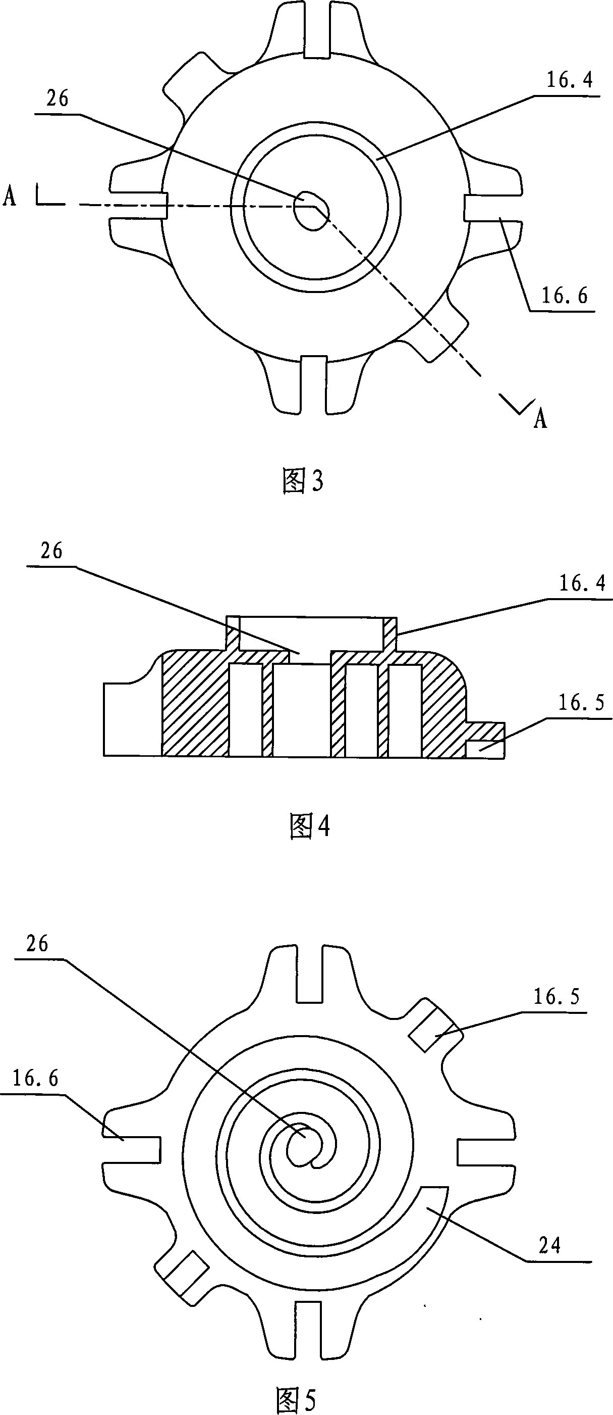
[0032]In the figure: 1 is the oiling through hole, 2 is the oiling blade, 3 is the oiling pipe, 4 is the lower bracket, 5 is the lower bearing assembly, 6 is the screw, 7 is the shell, 8 is the motor, 9 is the horizontal oil hole , 10 is the shaft, 11 is the frame, 11.1 is the supporting part, 11.2 is the assembly hole, 12 is the Oldham slip ring, 12.1 is the chute on the Oldham slip ring corresponding to the pair of keys of the rotating scroll, 12.2 is the chute with the static The key on the Oldham slip ring corresponding to the scroll chute, 13 is the rotating bearing, 14 is the oil supply hole of the compression chamber, 15 is the rotating scroll, 15.1 is the scroll, and 15.2 is the matching Oldham slip ring on the rotating scroll 15.3 is the protrusion on the back side of the orbiting scroll, 16 is the fixed scroll, 16.4 is the annular flange on th...


PUM


Abstract

The invention relates to a scroll-type compressor and a control method thereof. The scroll compressor comprises a static scroll plate, a rotary scroll plate, a frame, a motor, a shaft, a cross slip ring, an oil application component, bearings, a sealing element, an exterior support component and a case. Two high-pressure chambers and a low-pressure chamber are arranged inside the case of the compressor. The lower space of the case and the upper exhaust cavity of the static scroll plate communicated with the lower space of the case are a low high-pressure exhaust chamber and an upper high-pressure exhaust chamber, respectively. A motor is arranged inside the lower high-pressure exhaust chamber. A cavity in the middle of the case communicated with a suction passage is a low pressure suction chamber. The invention provides the pressure force to push the static scroll plate towards the rotary scroll plate in the way that a vent is communicated with the upper high-pressure exhaust chamber so that the end plate faces of the static scroll plate and the rotary scroll plate touch each other tightly when the scroll-type compressor works without failure; and the static scroll plate and the rotary scroll plate can be separated timely in case of exceptions, and the rotary scroll plate is effectively prevented from overturning.

Description

technical field [0001] The invention relates to a scroll compressor and a control method thereof. Background technique [0002] Existing scroll compressors include a fixed scroll with a scroll crimp on the bottom plate and a revolving scroll with a scroll crimp on the end plate, and the two scrolls mesh with each other Configuration that compresses fluid entering a scroll compressor by sequentially narrowing a plurality of compression chambers formed between mutual curls. Due to this compression action, an axial separation force that separates the fixed scroll and the orbiting scroll from each other is generated between the two scrolls. If the two scrolls are separated, there will be a large gap between the tooth tops and tooth bottoms of the two curls, which will cause the sealing performance of the compression chamber to deteriorate and the efficiency of the compressor to decrease. [0003] In order to solve this problem, the prior art proposes to form a back pressure ch...

Claims


Application Information

Patent Timeline
IPC IPC(8): F04C18/02F04C29/00
Inventor 邵海波
Owner MIDEA GRP CO LTD
Learn More