Steel tube concrete column-plate hinged joint node
A steel tube concrete column and concrete technology, which is applied in the direction of construction and building structure, can solve the problems of unbalanced bending moment, shear force, punching bearing capacity, etc., and achieve the effect of increasing deformation resistance and avoiding collapse
- Summary
- Abstract
- Description
- Claims
- Application Information
AI Technical Summary
Problems solved by technology
Method used
Image

Examples
Embodiment 1
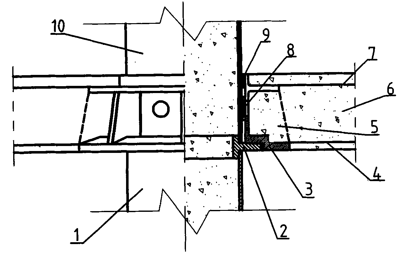
[0017] Referring to accompanying drawing 1, a concrete-filled steel tube column-slab hinge joint is composed of a concrete-filled steel tube concrete lower column 1, a hinged support lower plate 2, a hinged support upper plate 3, slab bottom longitudinal ribs 4, ribs 5, concrete floor slabs 6, The top longitudinal reinforcement 7, the horizontal push ring 8, the waterproof sealant 9, and the steel tube concrete upper column 10 are composed.
[0018] A hinged support lower plate 2 is installed between the steel tube concrete lower column 1 and the steel tube concrete upper column 10, the hinged support lower plate 2 is equipped with a hinged support upper plate 3, and the hinged support upper plate 3 is set on the steel tube concrete upper column 10 Above, between the upper plate 3 of the hinged support and the upper column 10 of concrete filled steel pipe, waterproof sealant 9 and horizontal push ring 8 are provided in sequence from top to bottom; the upper surface of the lower...
Embodiment 2
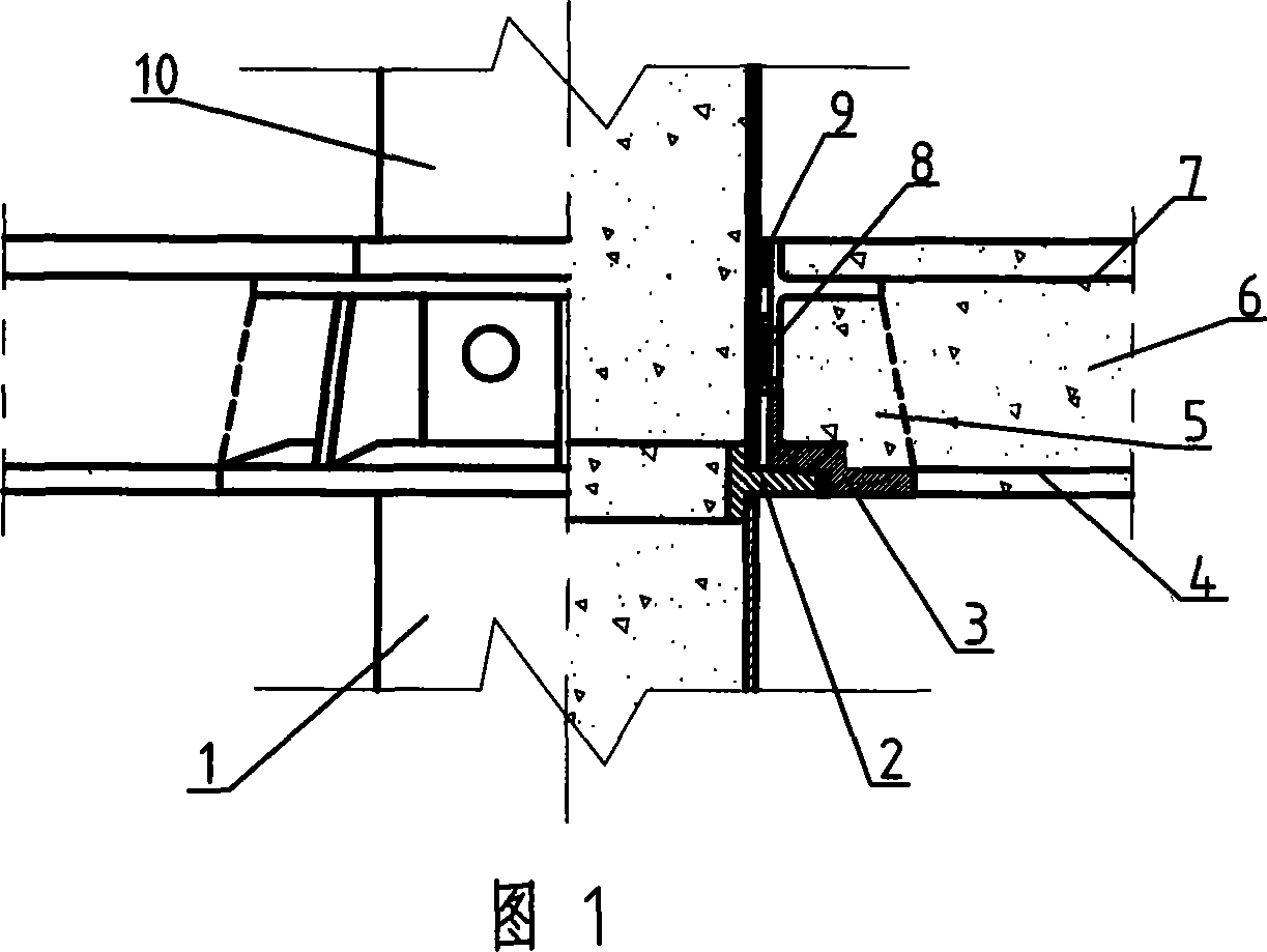
[0021] Referring to accompanying drawing 2, a concrete-filled steel tube column-slab hinged joint is composed of a concrete-filled steel tube lower column 1, a hinged support 2, a concrete floor 3, a steel reinforcement ring 4, a concrete-filled steel tube upper column 5, a slab top longitudinal reinforcement 6, and a slab bottom Composed of 7 longitudinal tendons.
[0022] A hinged support 2 is installed between the lower column 1 of the steel tube concrete and the upper column 5 of the concrete filled steel tube, the concrete floor 3 is supported on the hinged support 2, and a steel reinforcement ring connected with the upper column 5 of the steel tube concrete is provided above the hinged support 2 4. The slab top longitudinal reinforcement 6 and the slab bottom longitudinal reinforcement 7 in the concrete floor slab 3 are welded to the steel reinforcement ring 4 and the hinged support 2 respectively.
[0023] When the structure moves sideways, the hinged support 2 will pro...
Embodiment 3
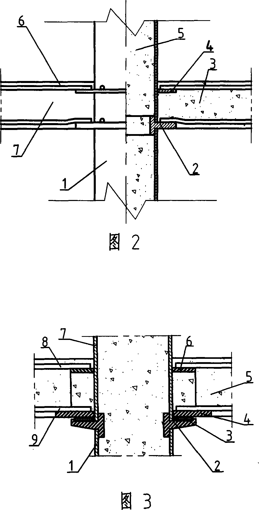
[0025] Referring to accompanying drawing 3, a concrete-filled steel pipe column-slab hinged joint consists of a concrete-filled steel pipe lower column 1, a hinged support 2, a copper gasket 3, a lower reinforcing steel ring 4, a concrete floor slab 5, an upper reinforcing steel ring 6, and a concrete-filled steel pipe Upper column 7, slab top longitudinal reinforcement 8, slab bottom longitudinal reinforcement 9 are formed.
[0026] A hinged support 2 is installed between the lower column 1 of the steel tube concrete and the upper column 7 of the concrete filled steel tube. The upper reinforced steel ring 6 connected to the upper column 7, the concrete floor 5 is supported on the hinged support 2 through the copper gasket 3 and the lower reinforced steel ring 4, and the upper part connected to the steel pipe concrete upper column 7 is arranged above the hinged support 2. The reinforcing steel ring 6, the longitudinal ribs 8 at the top of the slab and the longitudinal ribs 9 a...
PUM
 Abstract
Description
Claims
Application Information
 - Generate Ideas
- Intellectual Property
- Life Sciences
- Materials
- Tech Scout
- Unparalleled Data Quality
- Higher Quality Content
- 60% Fewer Hallucinations
Browse by: Latest US Patents, China's latest patents, Technical Efficacy Thesaurus, Application Domain, Technology Topic, Popular Technical Reports.
© 2025 PatSnap. All rights reserved.Legal|Privacy policy|Modern Slavery Act Transparency Statement|Sitemap|About US| Contact US: help@patsnap.com