Flexible circuit board press bonding method
A flexible circuit board and pressure technology, applied in chemical instruments and methods, lamination, printed circuits, etc., can solve problems such as difficult equipment and large area, and achieve the effects of improving peel strength, reducing glue overflow, and improving performance
- Summary
- Abstract
- Description
- Claims
- Application Information
AI Technical Summary
Problems solved by technology
Method used
Image
Examples
specific Embodiment approach 1
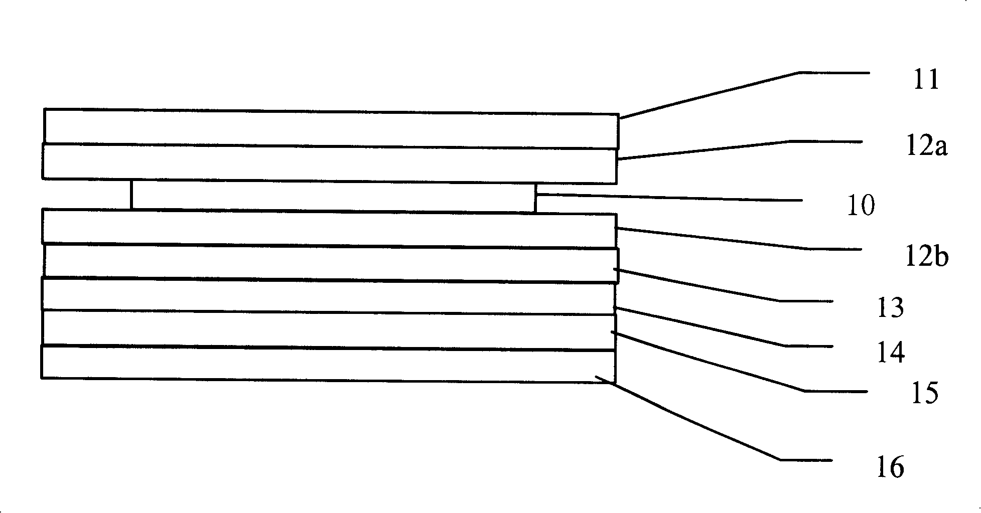
[0067] The first step of lamination is as follows: figure 1 The process conditions of the laminated plate structure shown are as follows:
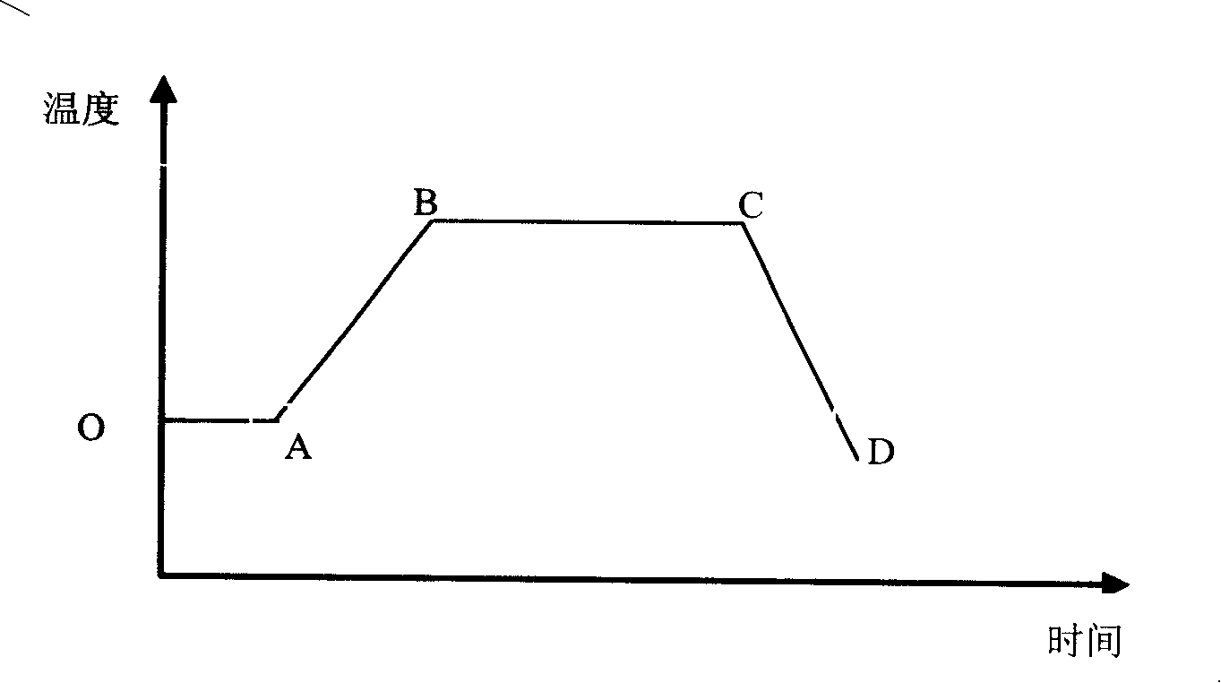
[0068] The pressing temperature process conditions of the first step of pressing are as follows:
[0069] Lamination Process Parameters
O
A
B
C
D
temperature(°C)
40
40
190
190
35
time (min)
0
10
55
85
135
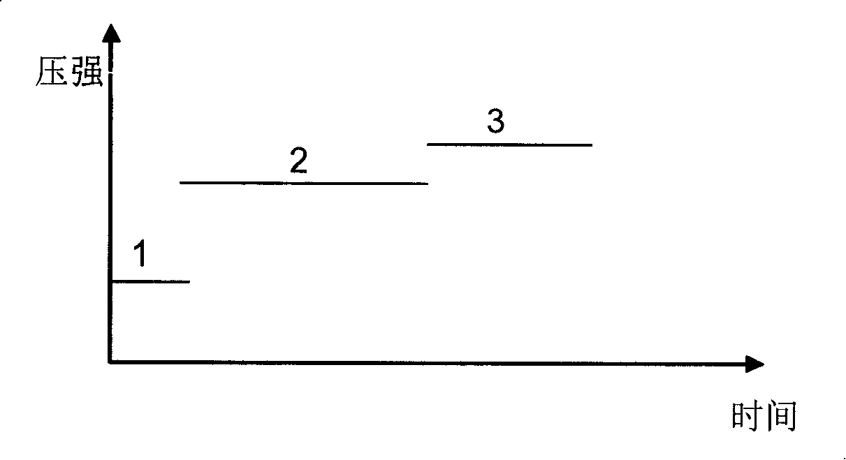
[0070] The pressure process conditions of the first step of lamination are as follows:
[0071] Lamination Process Parameters
starting point
Pressure: Pa(×10 6 )
0.62
0.62
2.4
2.1
time (min)
0
10
70
20
[0072] The second step of lamination adopts such as Figure 4 The process conditions of the laminated plate structure shown are as follows:
[0073] Temperature: 180°C;
[0074] Press...
specific Embodiment approach 2
[0077] The first step of lamination is as follows: figure 1 The process conditions of the laminated plate structure shown are as follows:
[0078] The pressing temperature process conditions of the first step of pressing are as follows:
[0079] Lamination Process Parameters
O
A
B
C
D
temperature(°C)
70
70
170
170
45
time (min)
0
5
80
125
155
[0080] The pressure process conditions of the first step of lamination are as follows:
[0081] Lamination Process Parameters
starting point
Paragraph 1
Paragraph 2
Paragraph 3
Pressure: Pa(×10 6 )
0.80
0.80
1.8
1.8
time (min)
0
15
90
50
[0082] The second step of lamination adopts such as figure 1 The process conditions of the laminated plate structure shown are as follows:
[0083] Temperature: 170°C;
[0084] Pressu...
specific Embodiment approach 3
[0087] The first step of lamination is as follows: figure 1 The process conditions of the laminated plate structure shown are as follows:
[0088] The pressing temperature process conditions of the first step of pressing are as follows:
[0089] Lamination Process Parameters
O
A
B
C
D
temperature(°C)
100
100
155
155
60
time (min)
0
20
110
170
190
[0090] The pressure process conditions of the first step of lamination are as follows:
[0091] Lamination Process Parameters
starting point
Paragraph 1
Paragraph 2
Paragraph 3
Pressure: Pa(×10 6 )
0.40
0.40
0.55
2.4
time (min)
0
20
120
80
[0092] The second step of lamination adopts such as Figure 4 The process conditions of the laminated plate structure shown are as follows:
[0093] Temperature: 190°C;
[0094] P...
PUM
 Abstract
Description
Claims
Application Information
 - R&D
- Intellectual Property
- Life Sciences
- Materials
- Tech Scout
- Unparalleled Data Quality
- Higher Quality Content
- 60% Fewer Hallucinations
Browse by: Latest US Patents, China's latest patents, Technical Efficacy Thesaurus, Application Domain, Technology Topic, Popular Technical Reports.
© 2025 PatSnap. All rights reserved.Legal|Privacy policy|Modern Slavery Act Transparency Statement|Sitemap|About US| Contact US: help@patsnap.com


