Free door controller
A door controller, free technology, applied in switches with brakes, door/window accessories, wing openers, etc., can solve the problems of difficult operation, time-consuming and laborious maintenance, complicated installation procedures, etc. Inexpensive, wide-ranging, and versatile effects
- Summary
- Abstract
- Description
- Claims
- Application Information
AI Technical Summary
Problems solved by technology
Method used
Image
Examples
Embodiment 1
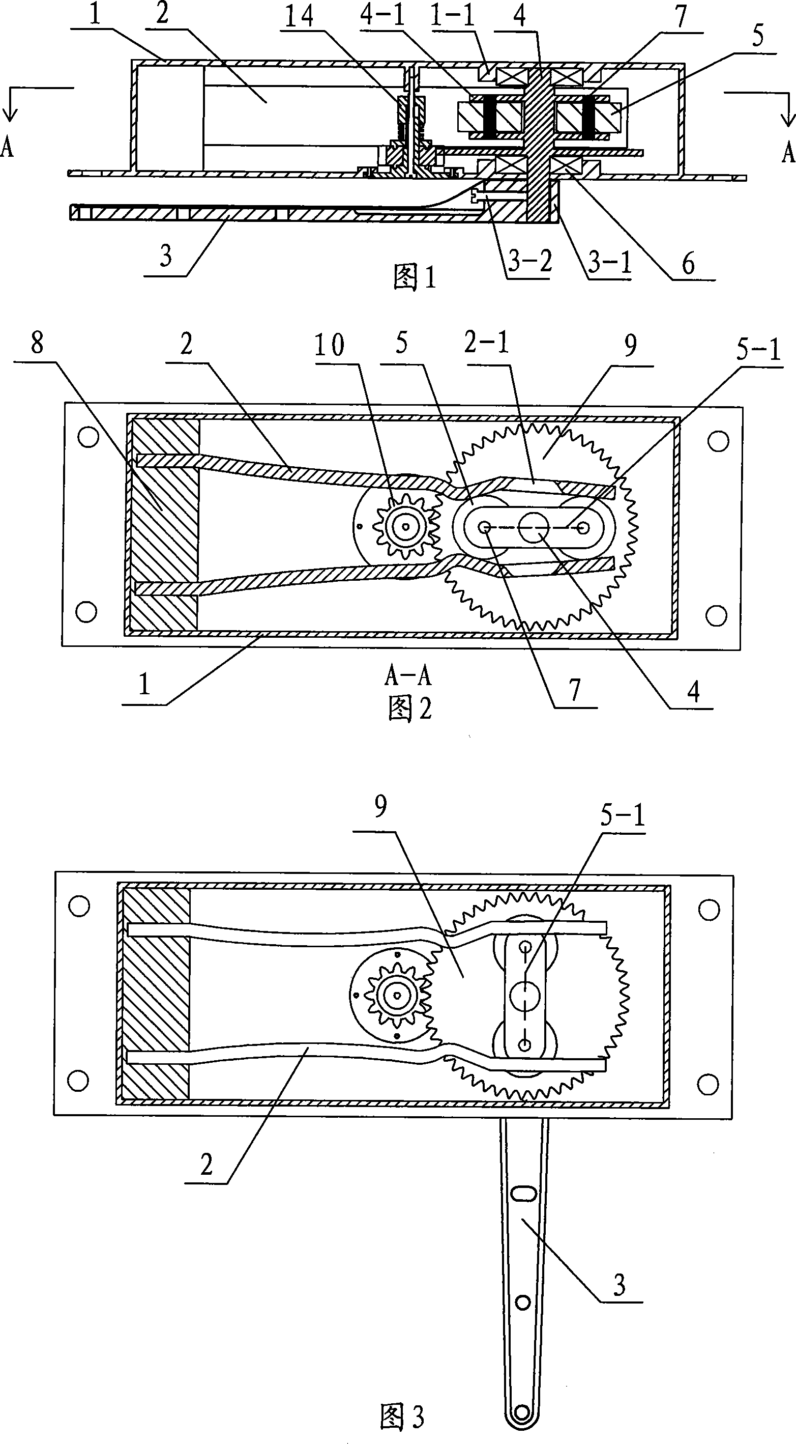
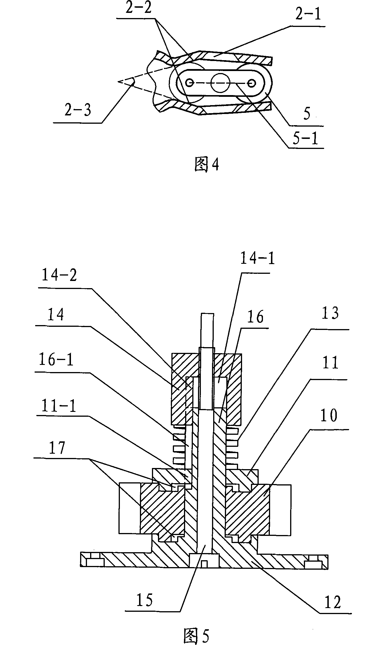
[0044] For the embodiment of the shaft rotation control device on the free door, see figure 1 , figure 2 , image 3 , Figure 4 and Figure 5 , a free door upper shaft rotation control device, including a housing 1, a speed regulating damping device, an elastic splint 2, a rotating connecting arm 3, a rotating upper shaft 4 and at least two rollers 5; The center is symmetrically installed on both sides of the rotating upper shaft; the rotating upper shaft is rotated and fixed between the upper and lower side plates in the housing, and one end of the rotating upper shaft extends out of the lower side plate of the housing; one end of the rotating connecting arm is fixed on the rotating shaft end The rotating upper shaft protrudes from one end of the casing, and the center line of the two rollers is parallel to the rotating connecting arm; one end of the elastic splint is fixed, and the other end of the elastic splint clamps the roller, and the speed regulating damping device...
Embodiment 2
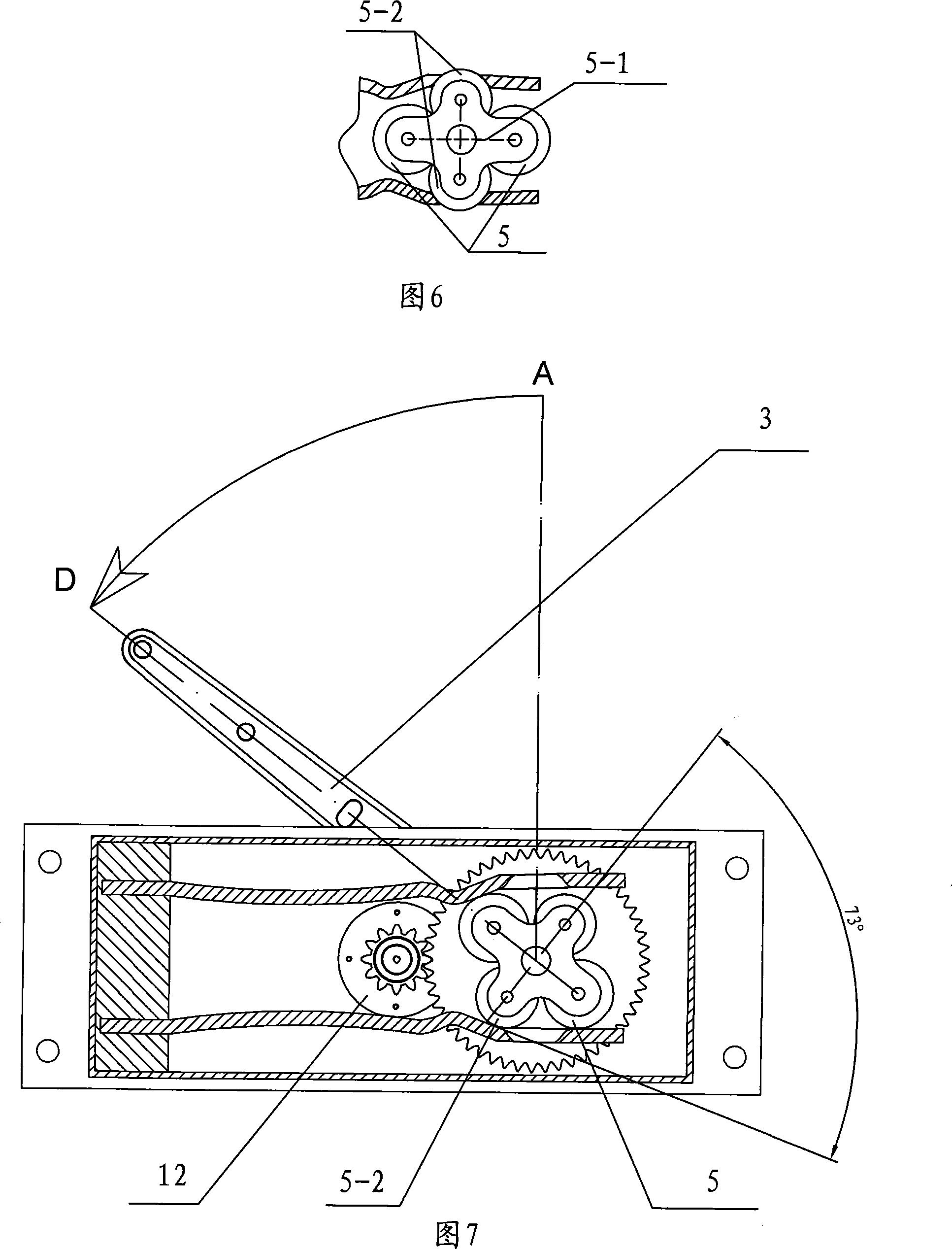
[0054] see Figure 6 , Figure 7 And embodiment 1, in order to improve the stability of the door in the closed state, and improve the wind resistance of the door when there is wind, two auxiliary rollers are added on the basis of embodiment 1, that is, in the shaft rotation control device of the free door There are four rollers. The diameters of the four rollers can be the same or different. The two rollers are divided into the first group and the second group. The two rollers of the first group are symmetrically installed on the rotating shaft as the center. On both sides of the upper shaft, the relative relationship of other parts of the two rollers of this group is the same as that of embodiment 1; the two rollers 5-2 of the second group are auxiliary rollers, symmetrically installed on both sides of the center line of the first group of rollers, And the center distance of the two rollers of the second group is smaller than the center distance of the two rollers of the fir...
Embodiment 3
[0056] see Figure 8 , Figure 9 , 10 And embodiment 1, different from embodiment 1 is: described elastic splint is two rigid splints 18 and extension spring 19; One end of two rigid splints is rotated and fixed by splint rotating shaft 20 in housing, and splint rotating shaft passes fixed block 21 and The splint rotating shaft bearing 22 is fixed on one end of the housing; the other end of the two rigid splints clamps the two rollers of the rotation; the extension spring is arranged between the two rigid splints to pull the two rigid splints, and the extension spring is arranged on the two rigid splints at the same time. The front end and the rear end of the roller clamped by the rigid splint can be respectively provided with one or more as required.
[0057] Figure 8 , Figure 9 It shows that when the door leaf of this embodiment is in the closed state, one end side of the two rigid splints clamps the two rollers at the same time through the action of the tension spring...
PUM
 Abstract
Description
Claims
Application Information
 - R&D
- Intellectual Property
- Life Sciences
- Materials
- Tech Scout
- Unparalleled Data Quality
- Higher Quality Content
- 60% Fewer Hallucinations
Browse by: Latest US Patents, China's latest patents, Technical Efficacy Thesaurus, Application Domain, Technology Topic, Popular Technical Reports.
© 2025 PatSnap. All rights reserved.Legal|Privacy policy|Modern Slavery Act Transparency Statement|Sitemap|About US| Contact US: help@patsnap.com


