Microwave sulphur lamp

A sulfur lamp and microwave technology, applied in the field of microwave sulfur lamps, can solve problems such as light failure

Inactive Publication Date: 2008-06-04
LG ELECTRONICS (TIANJIN) APPLIANCES CO LTD
View PDF0 Cites 1 Cited by
  • Summary
  • Abstract
  • Description
  • Claims
  • Application Information

AI Technical Summary

Problems solved by technology

[0005] The main technical problem to be solved by the present invention is to provide an improved microwave sulfur lamp so that it can be lit once and glow normally

Method used


Image

  • Microwave sulphur lamp
  • Microwave sulphur lamp
  • Microwave sulphur lamp

Examples


Embodiment Construction

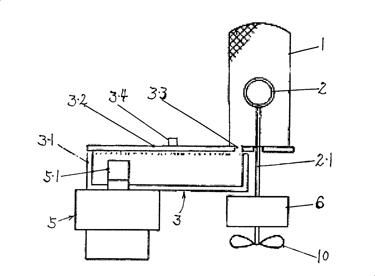
[0024] According to the technical plan, the author specifically made the following figure 2 The microwave resonant cavity shown is characterized in that a coupling antenna 1.1 is set at the position where the inner wall of the resonant cavity 1 is at the same height as the horizontal center of the bulb 2, thereby improving the resonance performance and shortening the lighting time of the bulb.

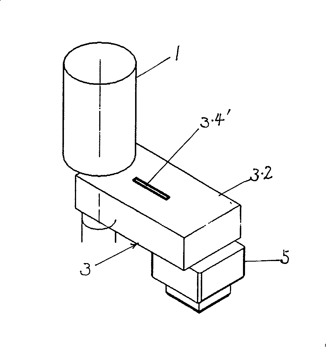
[0025] According to the technical plan, the author also made a technical transformation to the upper cover of the existing microwave waveguide cavity, canceling the block-shaped waveguide stub matching 3.4 fixed on the upper cover surface, and opening a A slit-shaped waveguide stub matching 3.4' is developed, which not only simplifies the fabrication of the waveguide stub matching, but also improves the microwave transmission efficiency of the waveguide cavity.

[0026] The above are only preferred embodiments of the present invention, and are not intended to limit the present inventi...


PUM


Abstract

The invention relates to a microwave sulfur lamp which consists of a magnetron, a microwave waveguide cavity consisting of an upper cover and a lower cavity, a bulb of the sulfur lamp and a microwave resonator for containing the bulb. The invention is characterized in that: a matching structure of waveguide stubs on the upper cover constituting the microwave waveguide cavity is openly arranged in a gap on the top of the upper cover, and a coupling antenna is internally arranged on an inner wall of the microwave resonator. By adopting the invention, the sulfur lamp can be lighted at a time and can shine normally.

Description

technical field [0001] The invention relates to a microwave sulfur lamp. Background technique [0002] Microwave sulfur lamps, using microwaves as energy sources, are transmitted to the resonant cavity through the waveguide cavity and cause the microwave to resonate in the resonant cavity. The excitation from the atomic state to the plasma state and an energy jump occurs when the sulfur reverts from the plasma state to form sulfur atoms, resulting in a continuum of spectra. Because this new type of light source has the advantages of energy saving, long service life, good light color and less pollution, it is very popular with people and has a broad prospect. [0003] like figure 1 As shown, the existing microwave sulfur lamp includes the following parts: a sulfur lamp bulb 2 and a magnetron 5 for generating microwaves, a waveguide cavity 3 for transmitting microwaves, and a microwave resonator for accommodating the sulfur lamp bulb. Cavity 1. The microwave output part 5 ...

Claims


Application Information

Patent Timeline
Patent Type & Authority Applications(China)
IPC IPC(8): H01J65/04
Inventor 任建伟
Owner LG ELECTRONICS (TIANJIN) APPLIANCES CO LTD
Why Eureka
Try Eureka