Magnetic-control sputtering coiling film coating machine
A technology of magnetron sputtering and coating machine, which is applied in sputtering coating, ion implantation coating, vacuum evaporation coating, etc. It can solve unfavorable economical operation of vacuum pump, large amount of gas outgassing, and inability to adapt to winding coating machine, etc. problems, to achieve the effect of smooth surface, low equipment cost, and dense surface microstructure
- Summary
- Abstract
- Description
- Claims
- Application Information
AI Technical Summary
Problems solved by technology
Method used
Image
Examples
Embodiment 1
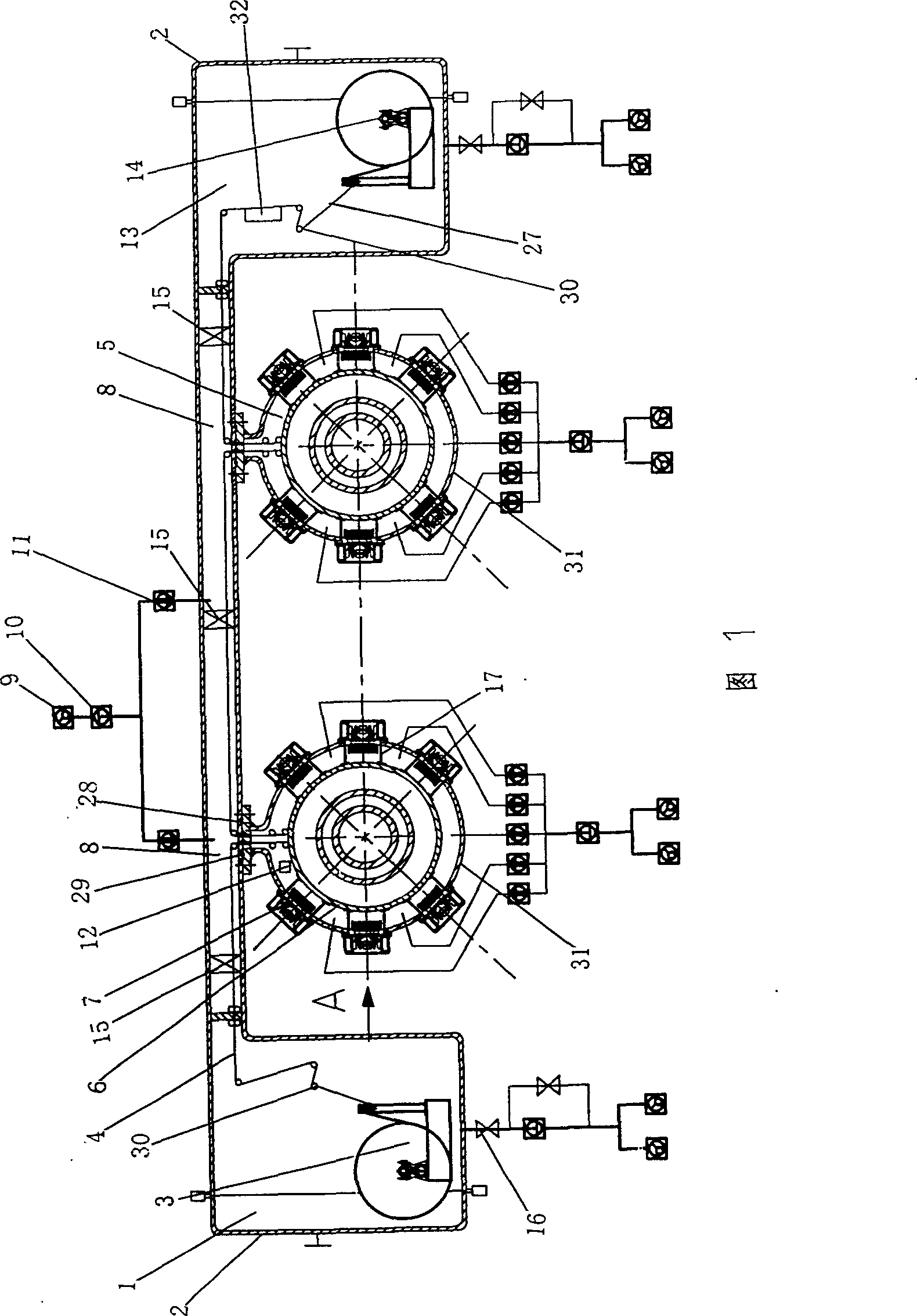
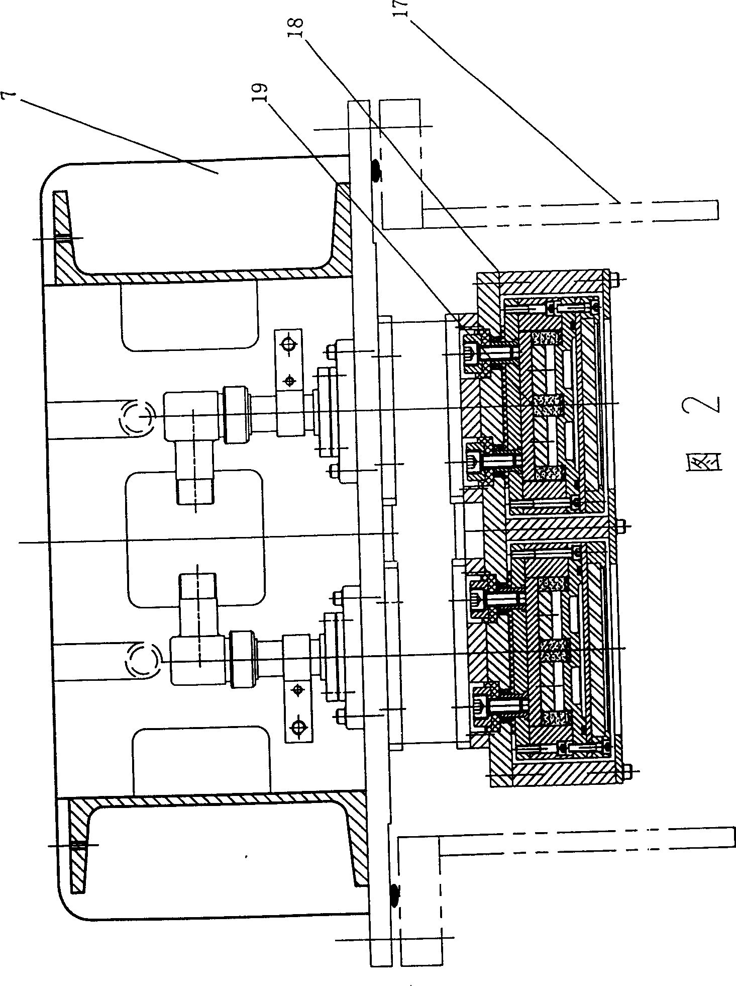
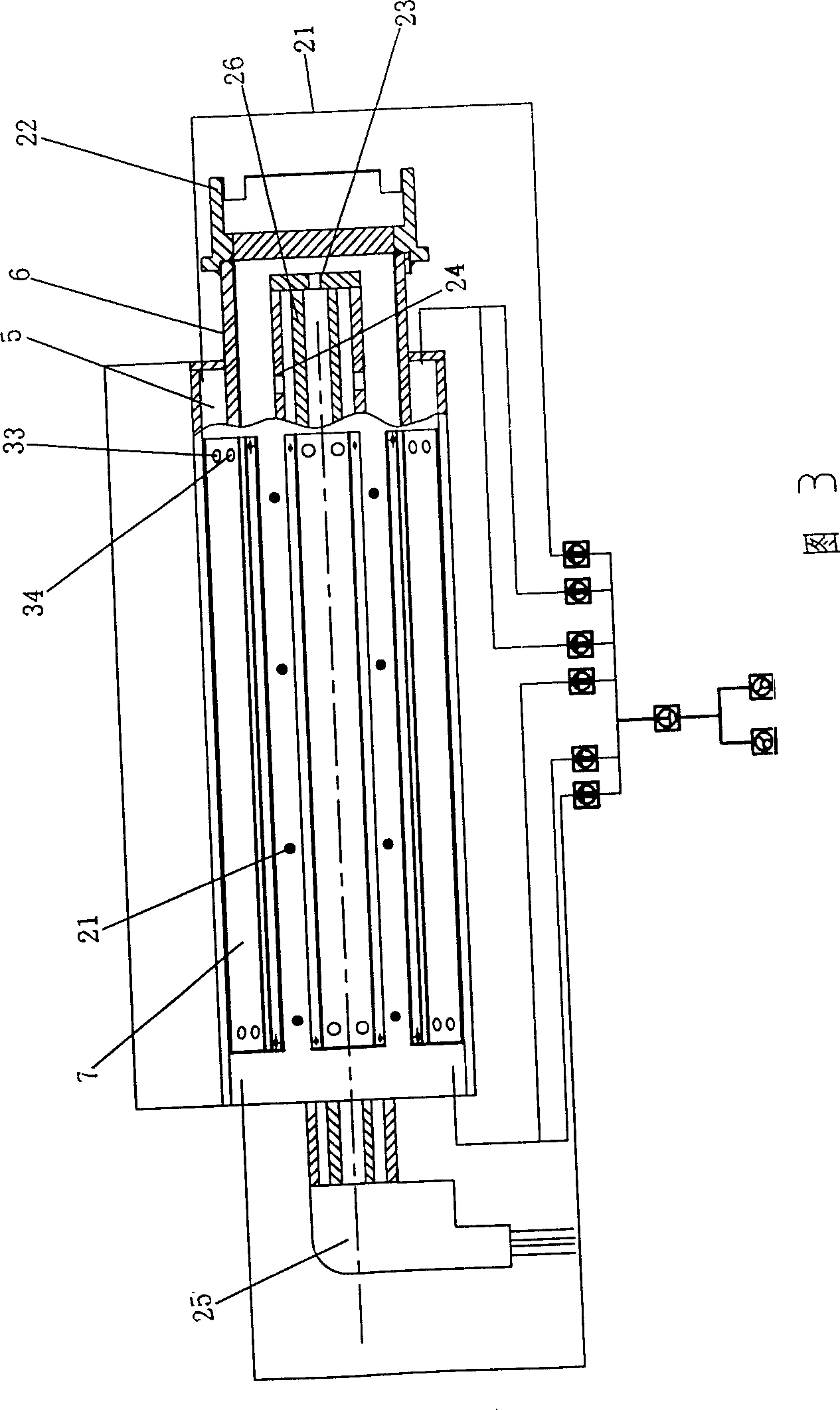
[0022] Fig. 1~Fig. 3 has provided the figure of embodiment 1 of the present invention. Referring to Fig. 1~Fig. 3, the structure diagram of magnetron sputtering roll-to-roll coating machine of the present invention, there is unwinding vacuum chamber 1 in the roll-to-roll coating machine of the present invention, is positioned at the opening that is used for changing coil material on the unwinding vacuum air wall Door 2, the unwinding machine located in the unwinding vacuum chamber 3, the film balance tension control system composed of several tension rollers in cooperation with the unwinding machine 30, the purchased film edge controller 32, the plastic film to be plated 4, Plated plastic film finished product 27, two coating vacuum chambers 5, two cooling rollers for cooling the film 6, twelve cathode flange connection seats 7, two vacuum coating boxes 31, vacuum connection box 8, for vacuuming Slide valve pump 9, Roots pump 10, molecular pump 11 for pumping high vacuum, stri...
Embodiment 2
[0025] Fig. 4 has provided the figure of embodiment 2 of the present invention. The structure of this embodiment 2 is basically the same as that of embodiment 1, except that two unwinding machines 3 are set in the unwinding vacuum chamber 1, and an automatic film splicing mechanism 31 is provided, which increases the speed of splicing the film and improves the production efficiency.
Embodiment 3
[0027] Fig. 1 and Fig. 5 have provided the figure of embodiment 3 of the present invention. The structure of Embodiment 3 is basically the same as that of Embodiment 1. The difference is that the cooling roller 6 is not powered to rotate, but is driven by the winder 14. The plastic film 4 is close to the cooling roller 6 to drive its rotation, reducing the transmission mechanism. , reduce equipment cost.
PUM
 Abstract
Description
Claims
Application Information
 - R&D
- Intellectual Property
- Life Sciences
- Materials
- Tech Scout
- Unparalleled Data Quality
- Higher Quality Content
- 60% Fewer Hallucinations
Browse by: Latest US Patents, China's latest patents, Technical Efficacy Thesaurus, Application Domain, Technology Topic, Popular Technical Reports.
© 2025 PatSnap. All rights reserved.Legal|Privacy policy|Modern Slavery Act Transparency Statement|Sitemap|About US| Contact US: help@patsnap.com


