Buffering bicycle frame

A bicycle and frame technology, which is applied in the field of cushioning bicycle frames, can solve problems such as uncomfortable shoulders and heads, unsatisfactory shock absorption effects, etc., and achieve the effects of reducing bearing capacity, alleviating vibration or collision, and reducing damage

Inactive Publication Date: 2008-06-04
王登高
View PDF0 Cites 2 Cited by
  • Summary
  • Abstract
  • Description
  • Claims
  • Application Information

AI Technical Summary

Problems solved by technology

Such vibrations make the rider's arms, shoulders and head very uncomfortable
Existing shock-absorbing bicycles all adopt the direct installation of shock-absorbing springs on the head tube for shock absorption. Such a technical solution can only reduce a part of the vibration in the vertical direction, and the shock-absorbing effect is not ideal.

Method used


Image

  • Buffering bicycle frame
  • Buffering bicycle frame
  • Buffering bicycle frame

Examples


Embodiment 1

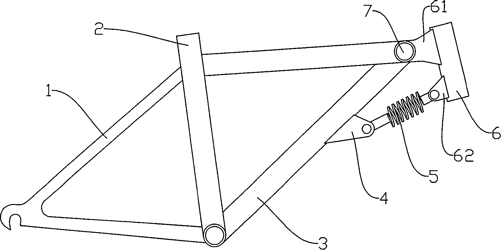
[0016] Embodiment 1, as attached figure 1 as shown in:

[0017] In this embodiment, the present invention includes a front tripod 3 and a rear tripod 1. In order to reduce the bearing capacity of the front fork and reduce the vibration of the headstock during travel, the present invention includes a headstock that is movably connected with the front tripod 3 Tube 6. A connecting piece is arranged on the head tube 6 , and a rotating shaft 7 is arranged on the connecting piece 61 , and the front tripod 3 is movably connected with the front tripod 3 through the rotating shaft 7 . A shock absorber 5 is arranged between the described head pipe 6 and the front tripod 3 . The shock absorber 5 is a shock absorber spring; one end of the shock absorber spring is connected to the front tripod through the connectors 4, 62, and the other end is connected to the head pipe 6. The connecting piece is to take and pay.

[0018] When the user needs to brake in an emergency or the road is rou...

Embodiment 2

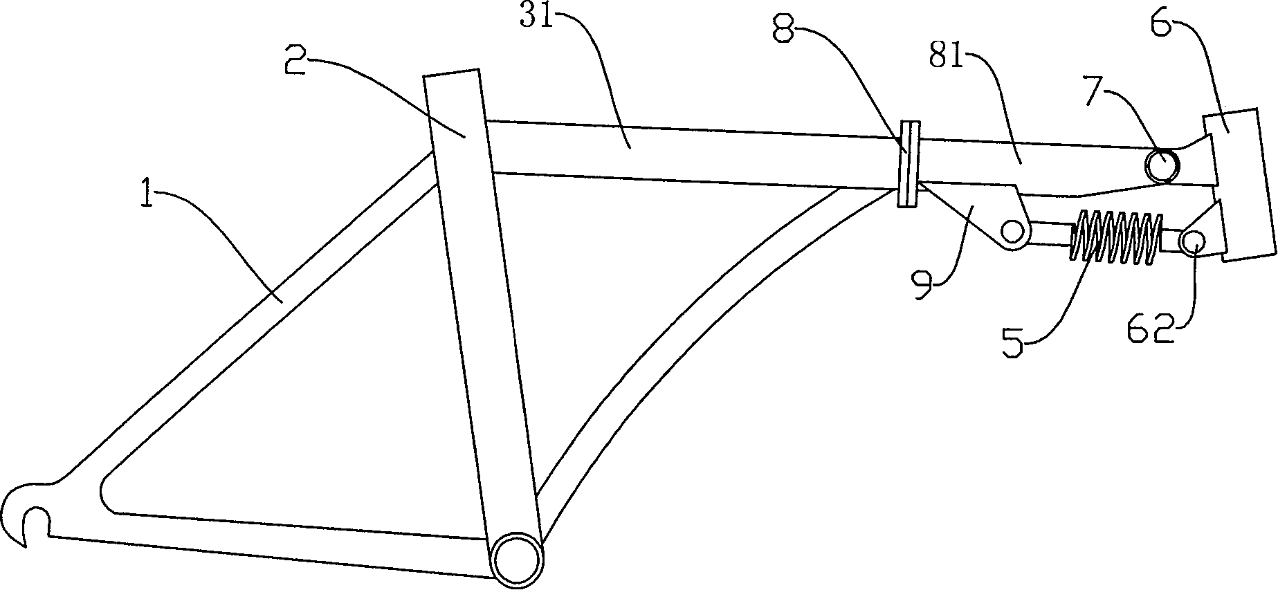
[0019] Example 2, such as figure 2 as shown in:

[0020] In this embodiment, the front tripod 3 is a folding front tripod with a folding shaft 8 , and the head end portion 81 of the folding front tripod is flexibly connected to the head tube 6 . A connecting piece 9 is arranged on the head end portion 81 of the front tripod 3 , the shock absorber 5 is connected to the connecting piece 9 , and the other end of the shock absorber is connected to the head pipe 6 .

[0021] The other parts of this embodiment are exactly the same as the embodiment.

Embodiment 3

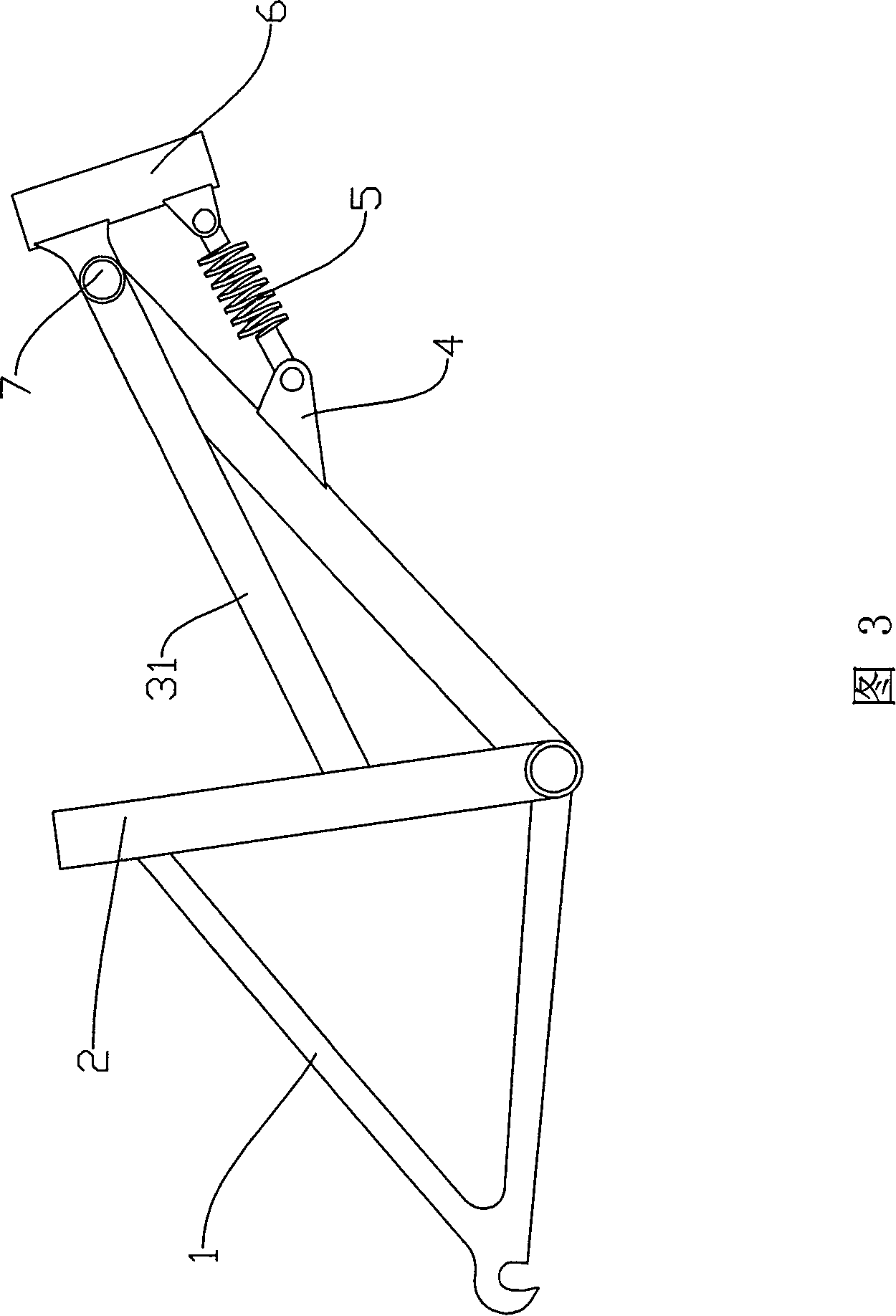
[0022] Embodiment 3, as shown in Figure 3:

[0023] In this embodiment, the front tripod 3 is a triangular front tripod, wherein the angle between the side of the beam 31 and the side of the vertical beam 2 is greater than 90°.

[0024] Other parts of this embodiment are the same as Embodiment 1.


PUM


Abstract

A buffering bicycle rack which belongs to the field of bicycles comprises a front tripod, a back tripod and a headstock tube and is characterized in that active connecting parts are arranged between the headstock tube and the front tripod; a shock absorber is arranged between the headstock tube and the front tripod; connectors which are arranged respectively on the headstock tube and the front tripod are connected to form an active rotating shaft point; the shock absorber is a shock-absorbing spring, and one end of the shock-absorbing spring is connected to the front tripod and another end of the shock-absorbing spring is connected to the headstock tube through the connectors. The invention changes the way of fixed connection of the headstock and the front tripod of the existing bicycles, by making use of a rotating shaft and the shock absorber, the invention facilitates the bicycle to release and absorb the jumping ability and the flinging resistance pressure, etc.; the invention also reduces various dangers caused by hard braking and collisions, etc., in the process of bicycle riding, which leads the bicycle riding to be more comfortable and safer; the endurance of front forks is reduced a plurality of times, thus releasing various vibrations or collisions, reducing the damage of bicycles and effectively prolonging the service life of the bicycle.

Description

Technical field: [0001] The invention designs a cushioned bicycle frame, which belongs to the field of human transportation tools, especially bicycles. Background technique: [0002] The head tube part of the existing bicycle is fixedly connected with the front tripod, and such a structure makes the head part always in a high-intensity vibration state when the bicycle is moving. Such vibrations make the rider's arms, shoulders and head very uncomfortable. Existing shock-absorbing bicycles all adopt to directly install shock-absorbing springs on the head tube for shock absorption, and such a technical scheme can only reduce a part of the vibration in the vertical direction, and the shock-absorbing effect is unsatisfactory. Invention content: [0003] The purpose of the present invention is to provide a buffer bicycle front tripod that can realize all-round shock absorption, reduce the vibration of the front part to the greatest extent, and ensure riding comfort. [0004] ...

Claims


Application Information

Patent Timeline
IPC IPC(8): B62K3/02
Inventor 王登高
Owner 王登高
Why Eureka
Try Eureka