Bulb steel production technology

A technology of production process and production process, applied in the direction of manufacturing tools, metal processing equipment, metal rolling, etc., can solve the problem of bulb flat steel process design, complex parameter calculation, surface scratches and unqualified specifications, and guide device High installation requirements and other issues, to achieve the effect of improving the overall performance of the product, small fluctuations in the size of the arc, and uniform force

Inactive Publication Date: 2008-06-04
ANGANG STEEL CO LTD
View PDF0 Cites 44 Cited by
  • Summary
  • Abstract
  • Description
  • Claims
  • Application Information

AI Technical Summary

Problems solved by technology

Bulb flat steel is composed of ball head and web, and can be divided into double-ball flat steel and single-ball flat steel in terms of cross-sectional shape. Because of its asymmetrical cross-sectional shape, the shape of the product will be twisted and bent during rolling, which increases the rolling capacity. Difficulty, and it is also prone to surface scratches and unqualified specifications and dimensions. Therefore, the process design and parameter calculation of bulb flat steel are extremely complicated, and the installation requirements for guide devices are also very high. Especially small-sized products are more difficult to roll. down (4 # ~16 #、 ) is rolled by a small section steel rolling mill, and it is impossible to roll these small-sized bulbous flat steels for a large rolling mill
[0003] The current split rolling technology has been widely used in the rolling of profiles, such as bars, wires, etc. The characteristics of these profiles are that the joint points at the splits have a small thickness and require a small splitting force, and these bars, Wire rods belong to building structures and have low requirements for dimensional accuracy, so the existing splitting technology is limited to the rod and wire rolling process

Method used


Image

  • Bulb steel production technology
  • Bulb steel production technology
  • Bulb steel production technology

Examples


Embodiment Construction

[0017] The present invention is characterized by adopting symmetrical rolling and straightening followed by splitting process, and its production process is: steel billet → heating → symmetrical rolling → straightening → splitting, each pass of the rolling mill consists of two symmetrical and equal Spherical flat steel pass configuration.

[0018] The technical characteristics of the present invention are:

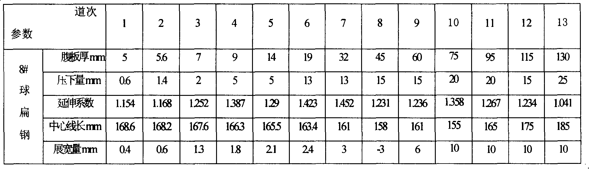
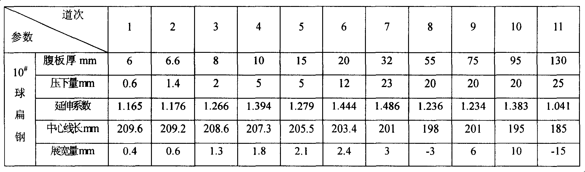
[0019] 1) The number of rolling passes is 9 to 13;

[0020] 2) Pass design:

[0021] a) Roll pass adopts symmetrical design;

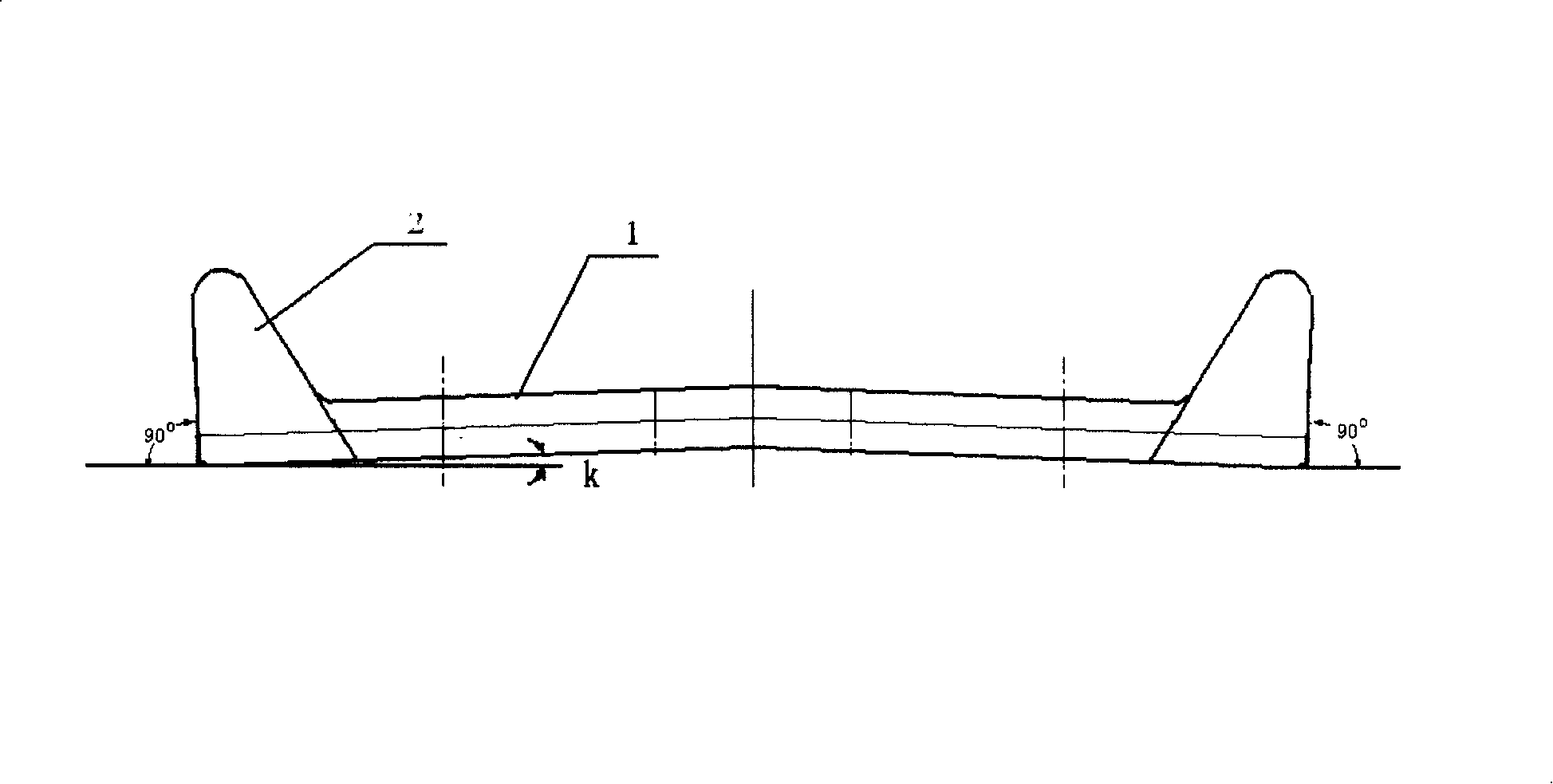
[0022] b) The finished hole and the re-front hole of the finished product adopt the ball head opening pass type, and the ball head side of the finished product front hole is open. Defects, ultimately ensuring the precise molding of the ball head and the outer surface of the ball head;

[0023] c) As shown in the figure, the inclination of the web 1 of the finished hole, the finished front hole, and the finished front hole of the roll is 4% to 7...


PUM


Abstract

The invention discloses a ball flat iron production technique, comprising steps of billet, heating, symmetrical rolling, straightening and dissection. The invention is characterized in that the dissection process is carried out after the processes of symmetric rolling and straightening; hole shapes in all the passages of a rolling mill are constituted by two ball flat iron hole shapes which are symmetrically identical. By adopting the technique of symmetric rolling, the invention solves the problems that existing large and medium rolling mills can not produce small ball flat irons with symmetrical rolling and dissection technology. The invention has the advantages of the small size fluctuation of profiles when producing, particularly the small size fluctuation of width, thickness, ball filling and the lower arc of the ball flat iron, rollers subject to uniform forces, easy control in rolling process, greatly reducing the scraping, the rolling mark and the waves of the product by 50% to 70%, improving the quality of the product, enlarging the types of rolled products, leading large profiled bar rolling mill to produce small ball flat iron, enlarging the profile of the billet, large corresponding compression ratio, improving the comprehensive performance of the products, etc.

Description

technical field [0001] The invention belongs to the field of metal processing, relates to a rolling process of profiles, in particular to a symmetrical rolling production process of spherical flat steel. Background technique [0002] Bulb flat steel is a special structural steel for ships and warships. It is used in conjunction with hull steel plates and is a key material for building various hull structures. Bulb flat steel is composed of ball head and web, and can be divided into double-ball flat steel and single-ball flat steel in terms of cross-sectional shape. Because of its asymmetrical cross-sectional shape, the shape of the product will be twisted and bent during rolling, which increases the rolling capacity. Difficulty, and it is also prone to surface scratches and unqualified specifications and dimensions. Therefore, the process design and parameter calculation of bulb flat steel are extremely complicated, and the installation requirements for guide devices are als...

Claims


Application Information

Patent Timeline
IPC IPC(8): B21B1/08B21B15/00B21B27/02B21B37/56
Inventor 唐复平黄浩东杜斌杨捷郑英杰董恩龙颜秉维刘鹤左岩张金明张业明
Owner ANGANG STEEL CO LTD
Why Eureka
Try Eureka