
Dual-boosting energy feedback type PWM rectification circuit

A rectifier circuit and energy-feedback technology, applied to electrical components, AC power input to DC power output, output power conversion devices, etc., can solve problems such as the body diode of the switch tube participating in the work, the hidden dangers of the bridge arm through-circuit, etc., to achieve Simple structure and low conduction loss

Inactive Publication Date: 2008-05-21
NANJING UNIV OF AERONAUTICS & ASTRONAUTICS
View PDF0 Cites 31 Cited by
  • Summary
  • Abstract
  • Description
  • Claims
  • Application Information

AI Technical Summary

Problems solved by technology

[0004] The purpose of the present invention is to provide a novel dual-boost energy-feedback PWM rectifier, which aims to retain the bidirectional energy flow characteristics of the traditional bridge-type energy-feedback PWM rectifier, and can overcome the bridge arm existing in the traditional bridge-type PWM rectifier circuit The disadvantages of shoot-through hidden danger and the body diode of the switch tube participating in the work

Method used


Image

  • Dual-boosting energy feedback type PWM rectification circuit
  • Dual-boosting energy feedback type PWM rectification circuit
  • Dual-boosting energy feedback type PWM rectification circuit

Examples


Embodiment Construction

[0015] The circuit structure and working principle of the embodiment of the present invention will be described below with reference to the accompanying drawings.

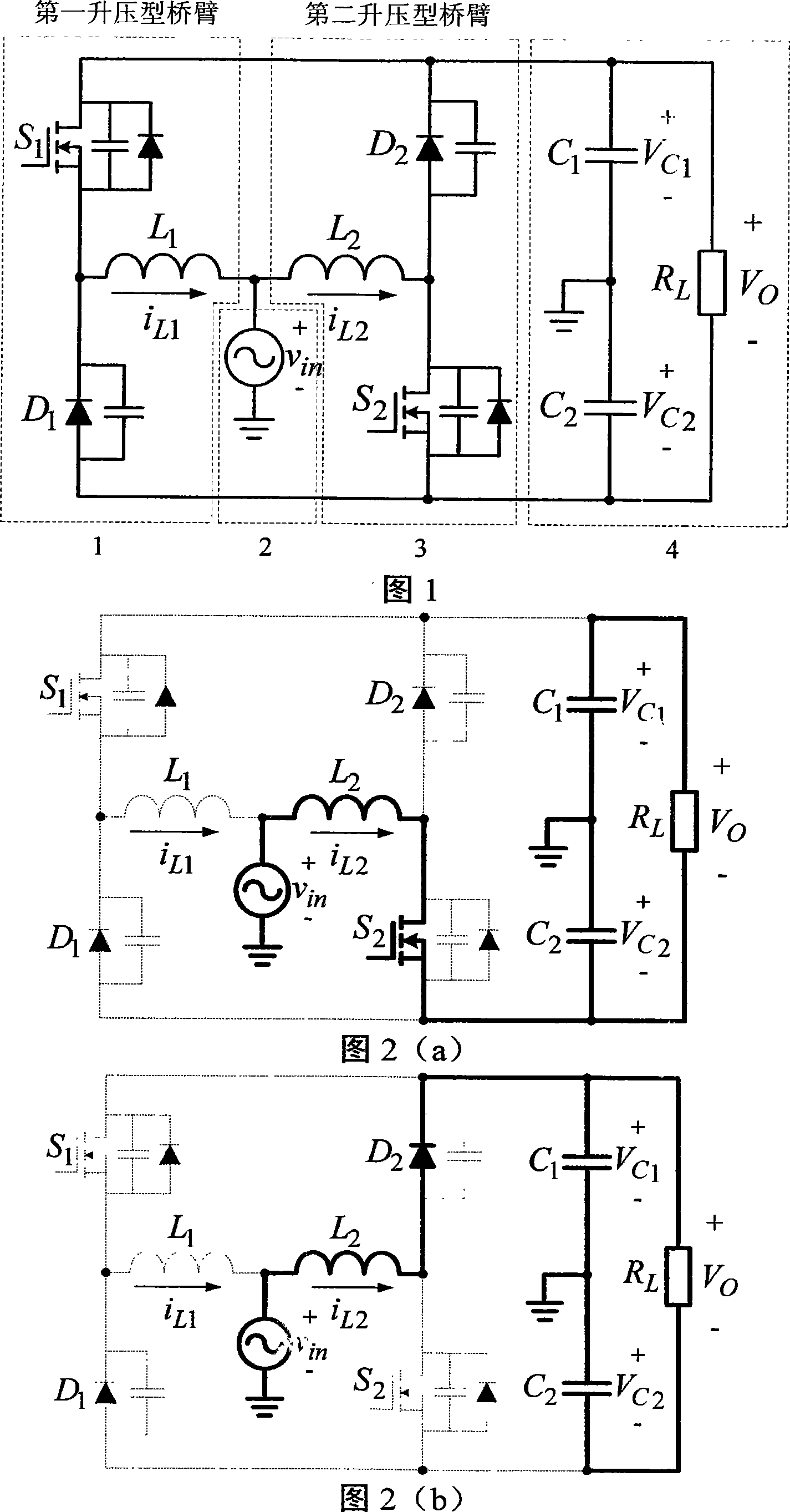
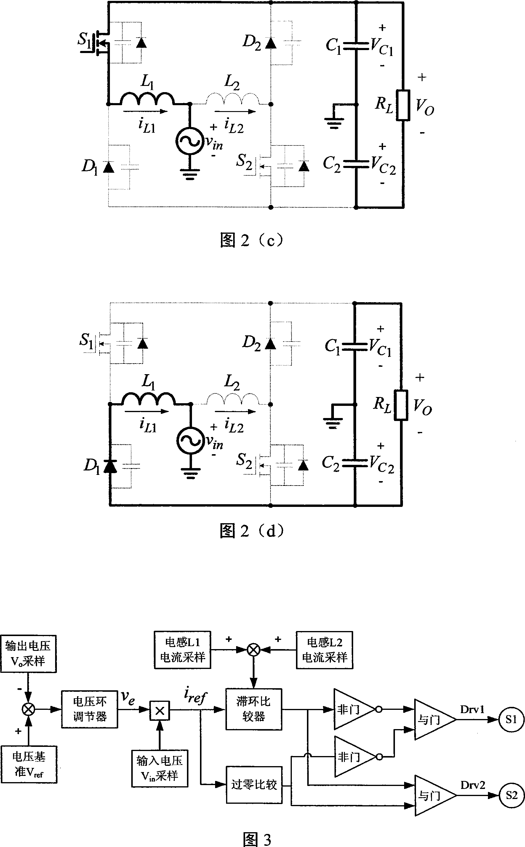
[0016] Accompanying drawing 1 is the structure schematic diagram of dual-boost energy-feedback PWM rectification circuit, and its circuit composition is, the input power supply v in The reference positive terminal of the first step-up bridge arm circuit unit 1 and the step-up inductance L 1 Connected to one end of the boost inductor L 1 , the other end of the power switch tube S 1 source and power diode D 1 Connected to the cathode of the power switch tube S 1 The drain and output filter capacitor C 1 The positive terminal is connected to the positive terminal of the output load, the power diode D 1 anode of the output filter capacitor C 2 The negative terminal of the output load is connected to the negative terminal, and the output filter capacitor C 1 negative terminal and output filter capacitor C 2 The ...


PUM


Abstract

The invention relates to a double-boost energy-feedback PWM rectifier circuit, which can work in an AC / DC rectification or DC / AC active inverter energy-feedback mode. It is composed of input power supply, two step-up bridge arm circuit units, output filter capacitor and load circuit. The first boost type bridge arm circuit unit is composed of a power switch tube, a power diode and a boost inductor; the second boost type bridge arm circuit unit is composed of a power switch tube, a freewheeling diode and a boost inductor; the output filter capacitor and load The circuit consists of two capacitors and a load. The two step-up bridge arm circuit units work in turn for half a power grid cycle, and the control circuit can select the corresponding step-up bridge arm circuit unit to work according to the positive and negative half cycle judgment of the input current. The energy of this circuit can flow bidirectionally, there is no bridge arm through problem, and the work reliability is high; only one power tube is chopped at high frequency in each switching cycle, and the loss is small. The rectification circuit has good application prospects in UPS, aerospace and other occasions.

Description

technical field [0001] The invention relates to a dual-boost energy-feedback PWM rectifier circuit. Background technique [0002] The wide application of power electronic products has caused serious harmonics to the power grid. Especially the traditional diode uncontrolled rectifier circuit and thyristor phase-controlled rectifier circuit, the power factor is low, the input current contains a large number of low-order harmonics, and the pollution to the power grid is particularly serious. PWM rectification technology can realize grid-side current tracking grid voltage, has many advantages such as high power factor, small size, high efficiency, etc. A wide range of applications has become one of the focus and hotspots of power electronics research. The traditional PWM rectifier circuit only works in the AC / DC rectification state, and the energy can only flow in one direction. However, in rail transit, large machine tools, etc., the drive motor works in the power generation ...

Claims


Application Information

Patent Timeline
IPC IPC(8): H02M7/219
Inventor 陈杰龚春英陈新张喻
Owner NANJING UNIV OF AERONAUTICS & ASTRONAUTICS
Learn More