
Semiconductor chip cleaning system

A technology for cleaning systems and semiconductors, applied in the manufacture of semiconductor/solid-state devices, electrical components, circuits, etc., can solve the problems of easily damaged wafers, reduced wafer productivity, uneven clamping conditions of clamping fingers, etc., to achieve cleaning effects, Improved wafer productivity, optimum cleaning performance

Inactive Publication Date: 2008-05-14
K C TECH
View PDF0 Cites 7 Cited by
  • Summary
  • Abstract
  • Description
  • Claims
  • Application Information

AI Technical Summary

Problems solved by technology

When the flat area wafer is inserted into the cleaning station under the condition that the flat area position of the wafer is not accurately aligned, the clamping conditions of each clamping finger are not uniform, so the wafer rotating at high speed is very easy to be damaged
In this way, wafer alignment must be required, thus becoming a lag in the overall process due to the time delay caused by the time required for alignment, which in turn reduces wafer throughput
[0008] In addition, existing semiconductor wafer cleaning systems have a large structure in which various cleaning, rinsing and drying stations are arranged in a row, thus requiring a large space for installation and application of prior art cleaning systems

Method used


Image

  • Semiconductor chip cleaning system
  • Semiconductor chip cleaning system
  • Semiconductor chip cleaning system

Examples


Embodiment Construction

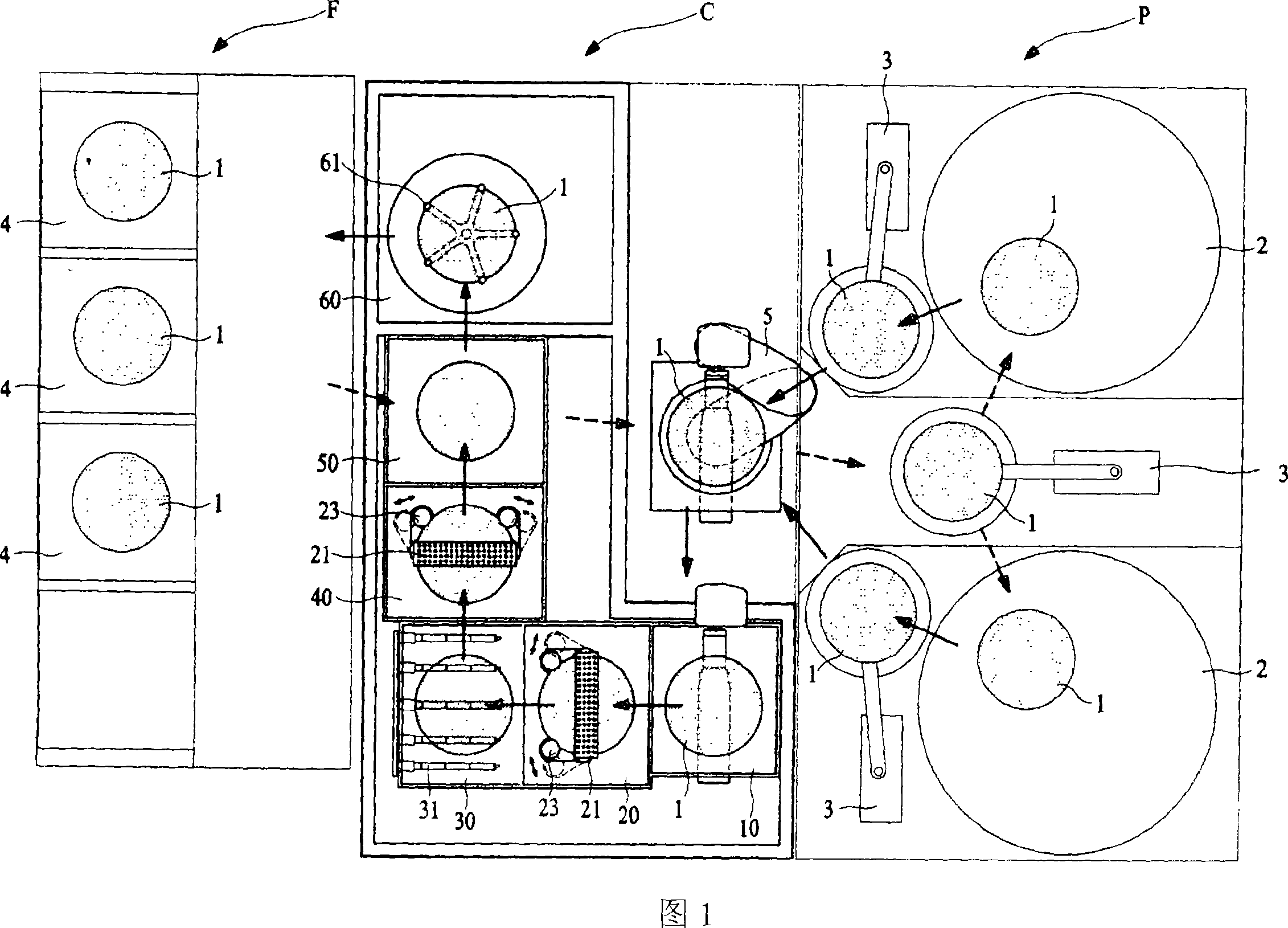
[0036] Hereinafter, a semiconductor wafer cleaning system according to a preferred embodiment of the present invention will be described in more detail with reference to the accompanying drawings.

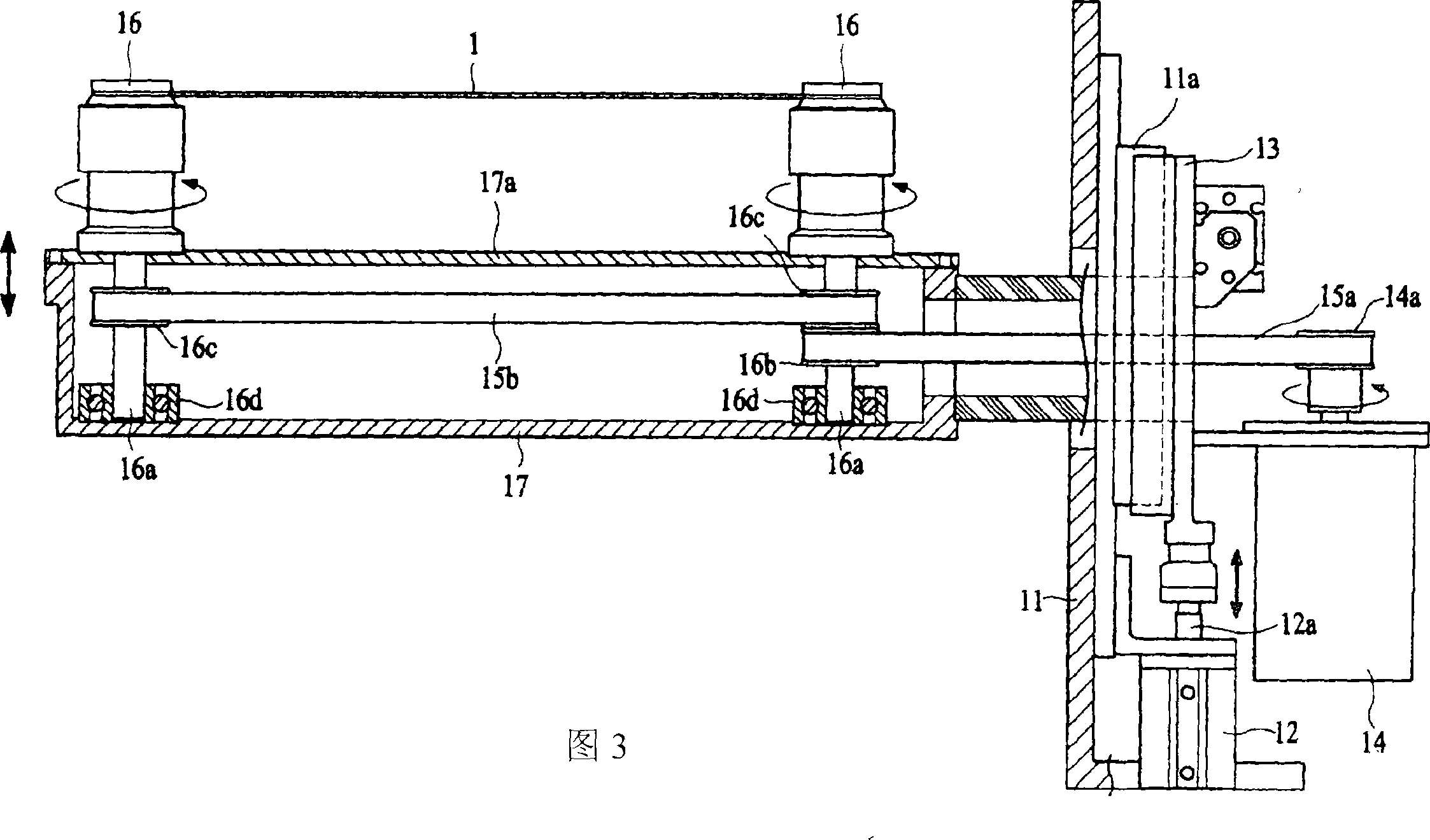
[0037] 1 to 11 are views explaining a semiconductor wafer cleaning system C according to the present invention. More specifically, Fig. 1 is a schematic diagram of the disposition structure of each part of the semiconductor wafer cleaning system C according to the present invention and its connection with peripheral devices such as a polishing module P and a wafer receiving module F in a plane; Fig. 2 is applied to A schematic diagram of the main structure of the pre-cleaning station 10 of the cleaning system C of the present invention, which is used to remove larger particles through the water curtain type injector 18 of deionized water; FIG. 3 is along the line shown in FIG. 2 Sectional view taken from III-III; Fig. 4 is a perspective view of the main structure of the first clean...


PUM


Abstract

The present invention related to a semiconductor wafer cleaning system comprising a preliminary cleaning station for removing particles on a wafer in advance by spraying deionized water thereon; a first cleaning station for cleaning remaining particles firstly by rotating frictionally a pair of brushes disposed to be contacted with a front surface and a back surface of the wafer and by spraying chemicals thereon through a chemical sprayer being provided independently; a first rinsing station for rinsing by spraying a cleaning liquid onto the firstly cleaned wafer at the first cleaning station; a second cleaning station for cleaning particles secondly remained on the front surface and the back surface of the wafer by spraying the chemicals onto the firstly rinsed cleaned wafer at the first rinsing station through a chemical sprayer being provided independently using the same structure and manner as those of the first cleaning station; a second rinsing station for rinsing by spraying the cleaning liquid onto the secondly cleaned wafer at the second cleaning station; and a dry station for drying the remained cleaning liquid using centrifugal force generated by rotating the rinsed wafer at the second rinsing station at a high speed. According to the present invention, a waiting time of entry into each cleaning station is minimized by processing a cleaning operation and a rinsing operation of a surface-polished wafer in a cleaning station and a rinsing station which are provided separately and independently thereby improves wafer productivity significantly by solving a delayed phenomenon in a whole process of wafer manufacturing.

Description

technical field [0001] The invention relates to a semiconductor wafer cleaning system. More particularly, the present invention relates to a semiconductor wafer cleaning system that causes wafers to enter the Wait times are minimized, increasing wafer throughput by eliminating delays throughout the wafer production process. Background technique [0002] In general, a semiconductor wafer manufacturing process includes a step of polishing the surface of the wafer by means of using a chemical mechanical polisher (CMP tool) or the like, and a step of cleaning the wafer to remove particles generated in the step of polishing the surface of the wafer. [0003] The step of cleaning the wafer is carried out in a number of different ways using various semiconductor cleaning systems currently known in the art. Typically, the steps of cleaning a wafer include spraying certain chemicals onto the wafer surface in a cleaning station, cleaning the wafer surface, and rinsing the wafer surf...

Claims


Application Information

Patent Timeline
IPC IPC(8): H01L21/304
Inventor 尹镇老金振泰
Owner K C TECH
Learn More