Large-scale thin optical screen digital video terminal

A digital video and thin light screen technology, applied in the field of digital video technology and applied optics, can solve the problems of low cost performance, unfulfilled technical potential, and high price

Inactive Publication Date: 2008-05-14
吴昆吾
View PDF0 Cites 0 Cited by
  • Summary
  • Abstract
  • Description
  • Claims
  • Application Information

AI Technical Summary

Problems solved by technology

Comparing these three technical methods, CRT technology is mature and cost-effective, but it is difficult to use it above 40 inches due to volume and weight limitations. PDP, LED, LCD, DMD, etc. have ...

Method used


Image

  • Large-scale thin optical screen digital video terminal
  • Large-scale thin optical screen digital video terminal
  • Large-scale thin optical screen digital video terminal

Examples


Embodiment Construction

[0018] Taking advantage of the image diagonal of DMD, Lcos and other devices less than 1 inch (Figure 3-6 It is the implementation diagram of optical path processing image magnification imaging, in Figure 3-6 In a, the light source H is reflected by the reflective bowl K to the convergent lens L 1 into parallel light, due to the red interference filter M R (reverse red and blue), blue interference filter M B (anti-blue through yellow) and green total reflection mirror M G (cyan + yellow = green) the three are different inclination angles and decompose the white light reflection into three primary color parallel lights diverging in three directions, passing through the trapezoidal prism L 2 The three primary color parallel lights that are corrected to be parallel in the same direction are reflected in the mirror M C Under the action of (subject to L V Synchronous control) The three primary color parallel light beams will swing left and right along the direction of the dotte...


PUM


Abstract

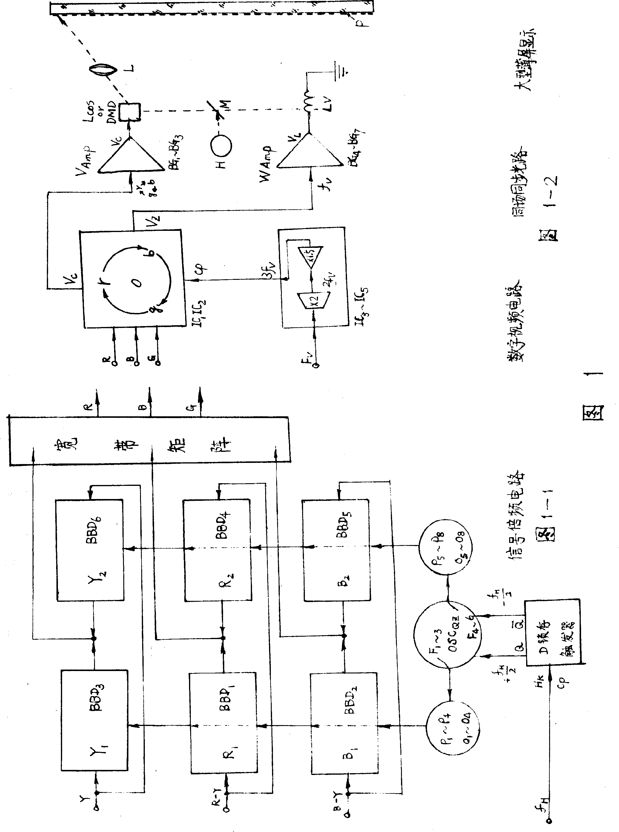
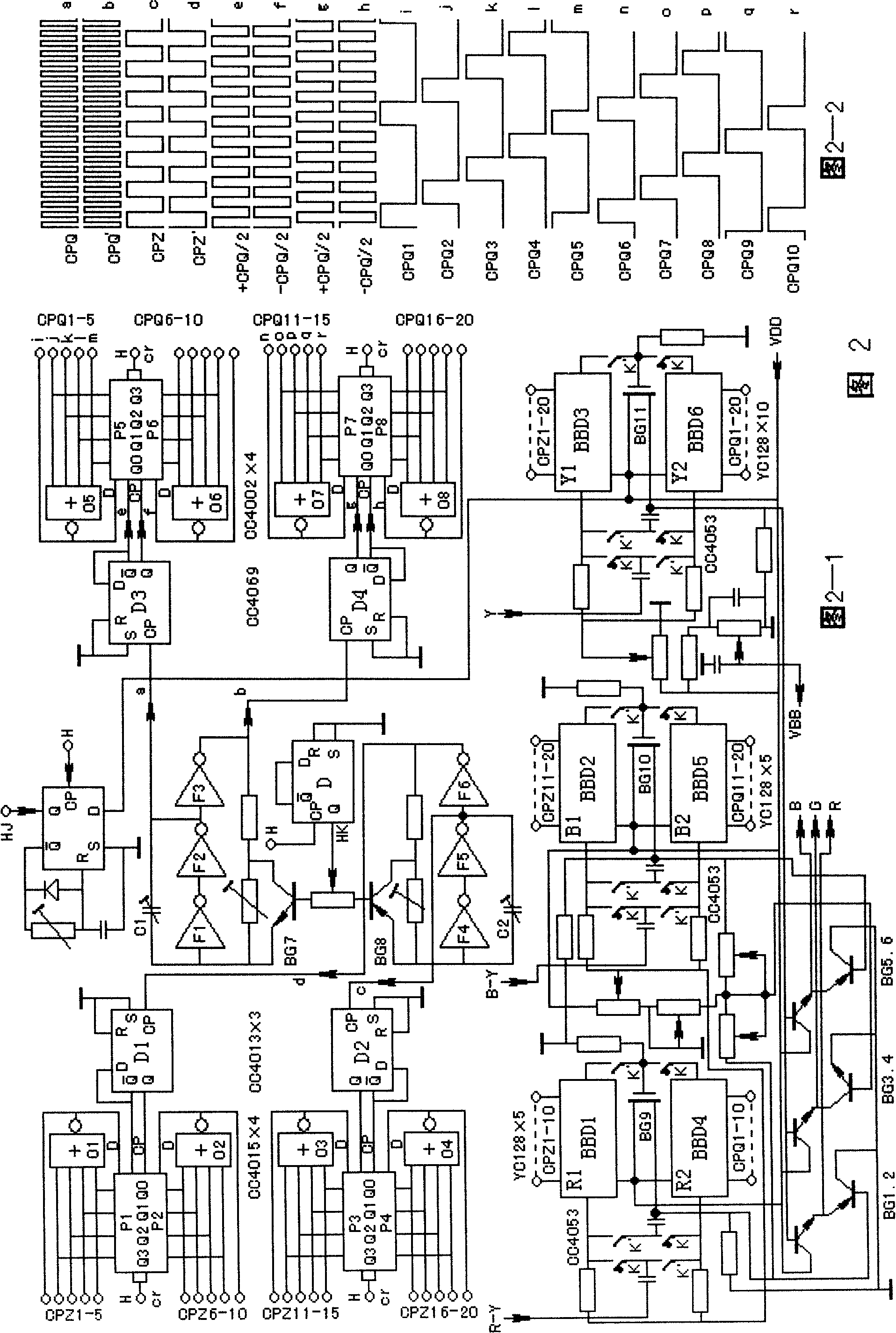
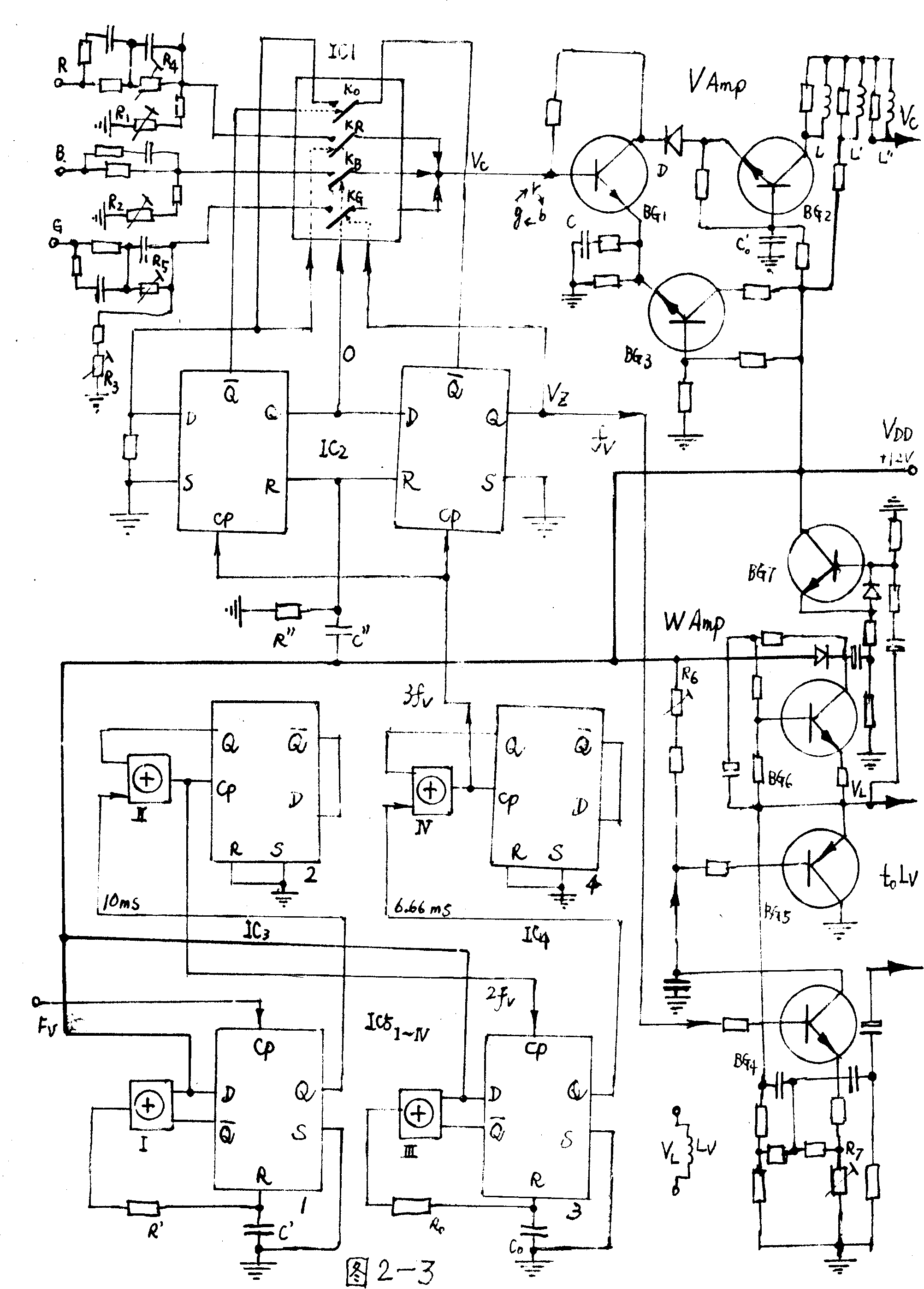
The invention provides a large-scale thin light screen digital video terminal, which relates to the digital video technology and applied optics technology field. In order to improve the performance and price ratio, the video processing circuit adopts the three-time speed time compression circuit composed of BBD components to acquire PDTV image signal, arranges a continuous zoom asymmetrical optical path before the image display to collaborate with the large field view and high efficiency triangle lens, and by combining with the half-way division of the anti-thin pack structure, adopts the 3fv field frequency to trigger and cyclically switch the tricolor synthesis serial source image signals; utilizing the synchronically flap mirror circuit same field driver source image display and via the bugeye lens oblique rays optical path, an ultra-large image is formed by an entire reflection and amplifying in the large-scale thin light screen. The implementation of the invention is of conventional process, with superior performance and cheap price, the efficiency of which greatly overruns the present flat-panel display technology.

Description

1. Technical field: [0001] The invention relates to the fields of digital video technology and applied optics technology. 2. Background technology: [0002] Since the turn of the 21st century, the world's electrical and optical display technologies have developed rapidly, and practical new technologies have emerged in an endless stream. Although there are various display methods, they can be generally classified into three categories: 1. The traditional CRT picture tube method that has been used for more than half a century And LED (light emittingdiode) light-emitting diode matrix display method, the PDP plasma screen method that has developed rapidly in recent years, and the latest SED (Surface-conduction Electronmitter Display) surface conduction electron emission display of Toshiba and Canon in Japan, these are active light-emitting displays Way. 2. Using the LCD liquid crystal display method of about a quarter of a century, the Lcos (Liquid Crystal on Silicon) liquid cr...

Claims


Application Information

Patent Timeline
IPC IPC(8): H04N9/12G02B17/08
Inventor 吴昆吾
Owner 吴昆吾
Why Eureka
Try Eureka