
Air conditioner oil returning system

An oil return system, air conditioner technology, applied in refrigeration safety arrangements, refrigerators, lighting and heating equipment, etc., can solve the problems of compressor 11 damage, low suction pressure of compressor 11, easy to generate noise, etc. Work effect, reduce the possible effect of refrigerant backflow

Inactive Publication Date: 2008-05-14
HAIER GRP CORP +1
View PDF0 Cites 12 Cited by
  • Summary
  • Abstract
  • Description
  • Claims
  • Application Information

AI Technical Summary

Problems solved by technology

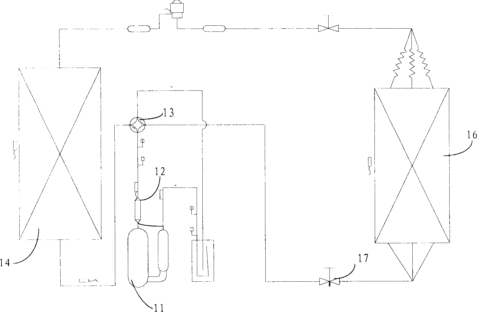
The fast-flowing gas mixture passes through the oil separation device 12, and a part of the oil is taken out of the oil separation device 12 by the fast-flowing refrigerant gas before it is separated from the gas refrigerant, and enters the evaporator 16 directly or indirectly, which affects the system performance of the air conditioner. heating and cooling effect
[0005] In the air conditioner, the oil separator 12 also plays the role of noise reduction, but it can only eliminate the noise generated when the compressor 11 is exhausted.
When the air conditioner is heating, the high-temperature and high-pressure refrigerant gas directly enters the indoor evaporator 16 to dissipate heat. When the high-pressure gas passes through the gas-side stop valve 17, the flow rate is fast, and noise is likely to be generated during the throttling and pressure-reduction process, which affects the indoor environment. people's work and life
[0006] The oil separation device 12 cannot effectively prevent liquid back phenomenon
When the air conditioner is heating, the outdoor temperature is often low, it is difficult for the wet vapor of the refrigerant to absorb heat in the condenser 14, the refrigerant evaporates less, the suction pressure of the compressor 11 is low, and the liquid refrigerant easily enters the compressor 11, resulting in compression. Machine 11 damaged
[0007] Therefore, the existing oil separator 12 is difficult to effectively separate the oil and the refrigerant when the air conditioner is working, which affects the working effect of the air conditioner.
And when the air conditioner is heating, it cannot effectively eliminate the noise and prevent the phenomenon of liquid return.

Method used


Image

  • Air conditioner oil returning system
  • Air conditioner oil returning system
  • Air conditioner oil returning system

Examples


Embodiment Construction

[0026] In order to make the above objects, features and advantages of the present invention more comprehensible, the present invention will be further described in detail below in conjunction with the accompanying drawings and specific embodiments.

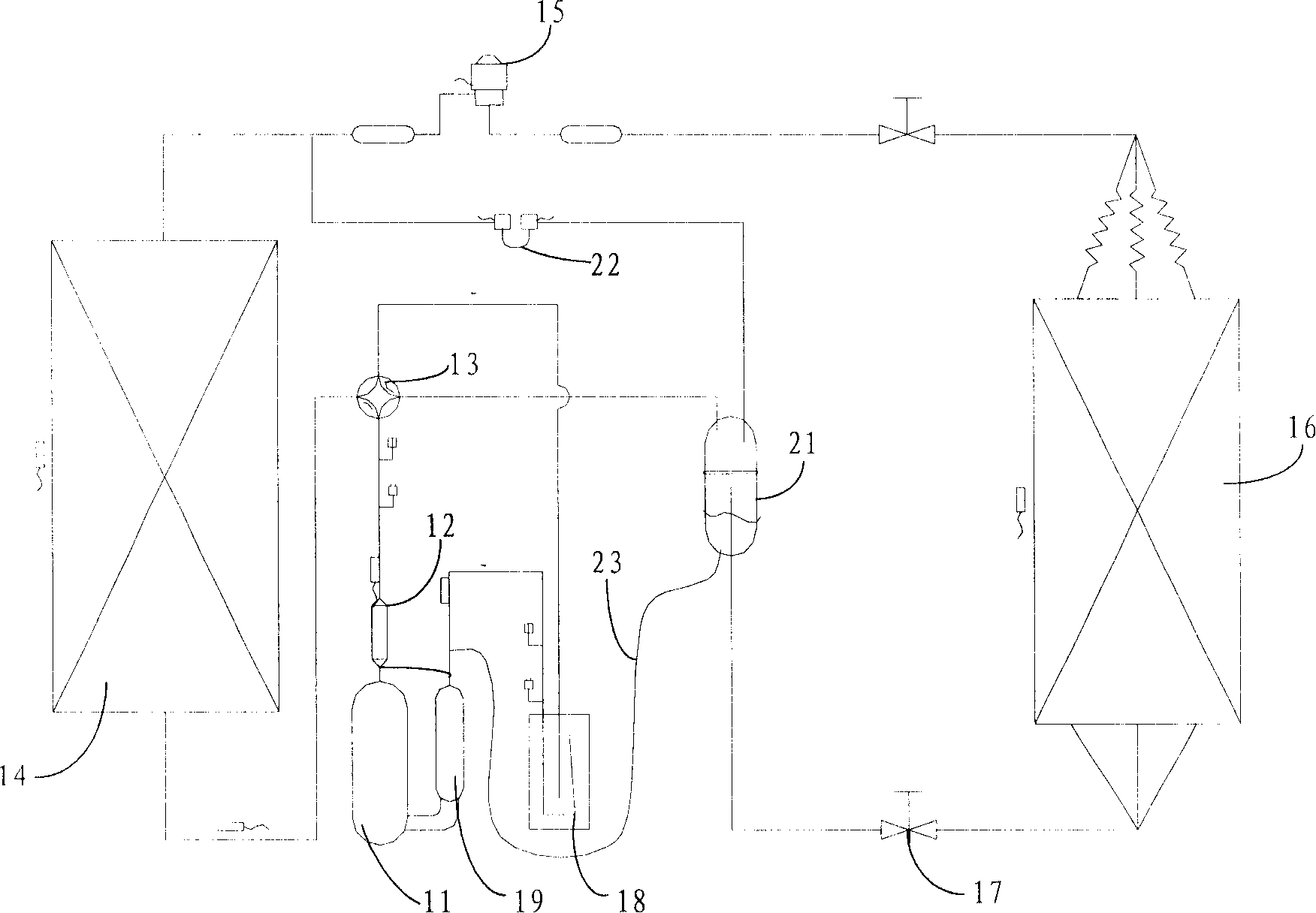
[0027] The core idea of ​​the present invention is to install an oil separator between the four-way valve and the evaporator, and the oil separator can be connected to the condenser through the electromagnetic valve, and connected to the suction pipe of the compressor through the oil return capillary. When the air conditioner is working, by controlling the opening and closing of the solenoid valve and the expansion valve, the internal pressure of the oil separator is effectively controlled, and the low pressure on the suction side of the compressor is used to automatically complete the oil return, realizing the effective compensation of secondary oil return and automatic oil separation An oil separation device is installed at the e...


PUM


Abstract

The invention discloses an oil-return system used for an air conditioner, comprising a compressor, a four-way valve, a condenser, an expansion valve, an evaporator, an air-side check valve, as well as an oil separator, a solenoid valve and an oil-return capillary. The oil separator is connected with the four-way valve and the evaporator. The solenoid valve is connected with the oil separator and the condenser. The oil-return capillary is connected with the oil separator and the compressor. When the air conditioner works, the invention can effectively separate the oil from cooling mediums to enhance the working efficiency of the air conditioner, which can further eliminate noises and avoid the happening of cooling liquid returning.

Description

technical field [0001] The invention relates to the field of air conditioners, in particular to an oil return system for an air conditioner. Background technique [0002] Air conditioners are one of our most commonly used household appliances. Air conditioners use compressors to compress refrigerants, and use the refrigerants to absorb and release heat to achieve cooling and heating functions. During the process of compressing the refrigerant, the compressor needs lubricating oil to lubricate its parts to prevent mechanical failure and improve the service life of the compressor. However, if the lubricating oil and the refrigerant are mixed together and enter the evaporator for refrigeration and heating cycles, the cooling and heating effects of the air conditioner will be affected. Therefore, the lubricating oil must be separated from the refrigerant through the oil return system and sent back to the compressor. machine for recycling. [0003] refer to figure 1 , is a sch...

Claims


Application Information

Patent Timeline
Patent Type & Authority Applications(China)
IPC IPC(8): F25B31/00F25B49/02
Inventor 张晓兰国德防崔国宝赵振立
Owner HAIER GRP CORP
Learn More