
Continuously variable transmission, drive device, and method of controlling the drive device

A continuously variable transmission and continuously variable speed technology, which is applied in transmission control, mechanical equipment, transmission boxes, etc., can solve the problems of increased cost, shortened bearing life, increased thrust load of radial bearings, etc., to prevent centrifugal hydraulic pressure Produces and prevents the reduction of bearing life and reduces the effect of axial pressure

Inactive Publication Date: 2008-05-07
DAIHATSU MOTOR CO LTD
View PDF1 Cites 4 Cited by
  • Summary
  • Abstract
  • Description
  • Claims
  • Application Information

AI Technical Summary

Problems solved by technology

However, in this case, there are problems in that a thrust bearing needs to be arranged between the intermediate wall and the forward and reverse motion conversion device, and the number of parts increases, the cost increases, and the axial dimension increases because the strength of the intermediate wall needs to be ensured
Therefore, there is a problem that the thrust load to the radial bearing increases and the life of the bearing becomes short
Although this problem can be solved by increasing the size of the bearing, there is a disadvantage of increased cost and increased size

Method used


Image

  • Continuously variable transmission, drive device, and method of controlling the drive device
  • Continuously variable transmission, drive device, and method of controlling the drive device
  • Continuously variable transmission, drive device, and method of controlling the drive device

Examples


example 1

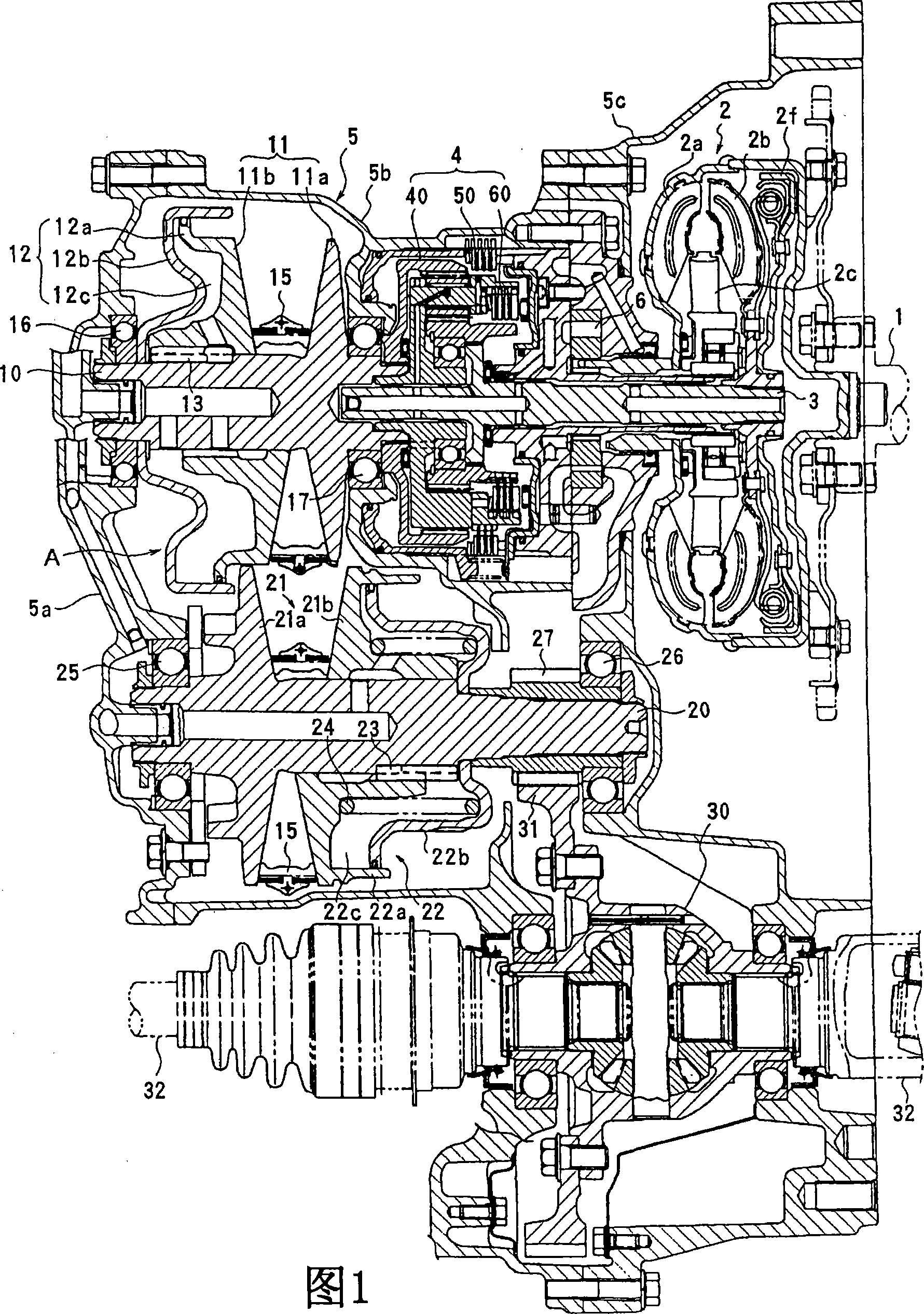
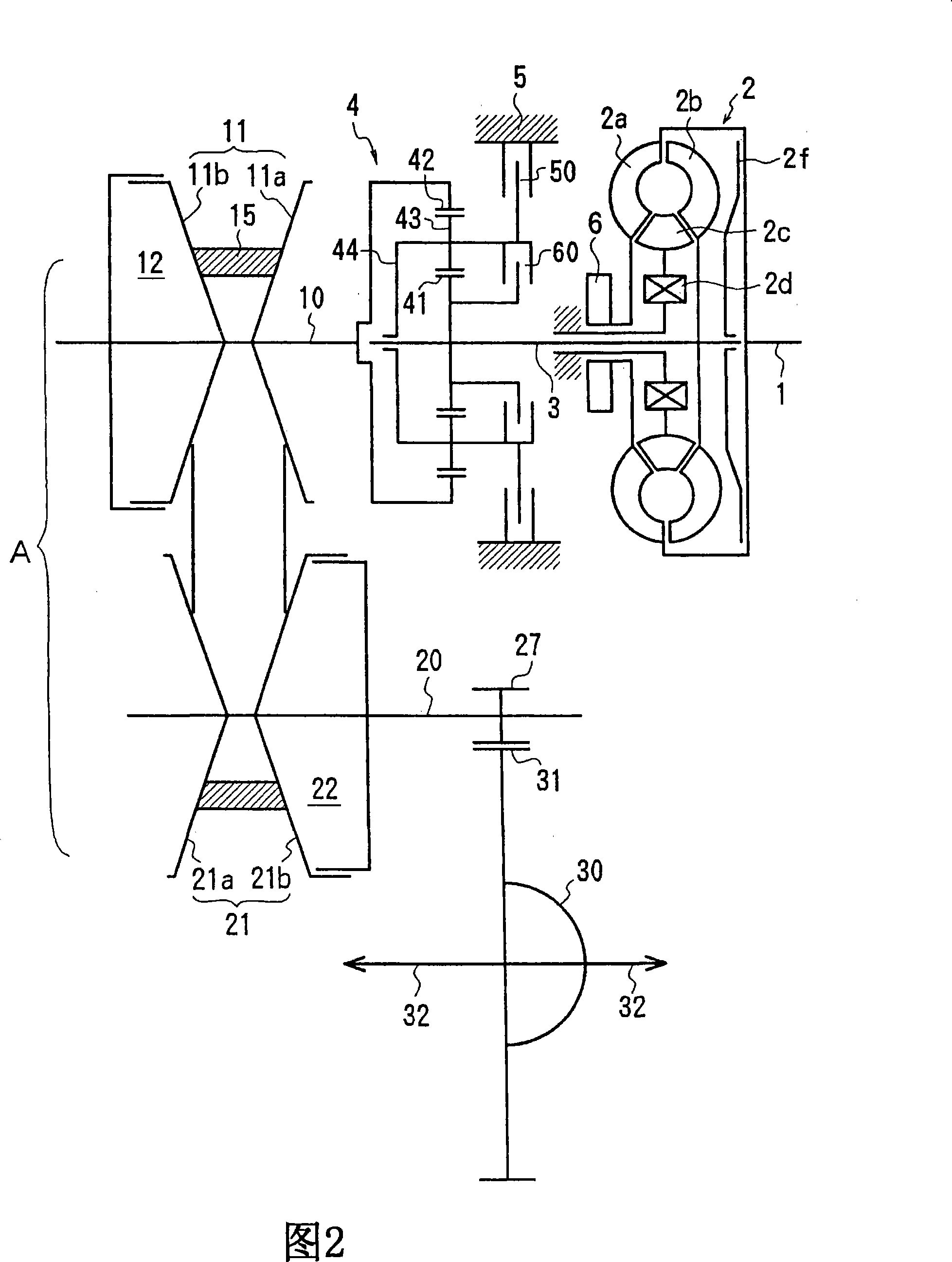
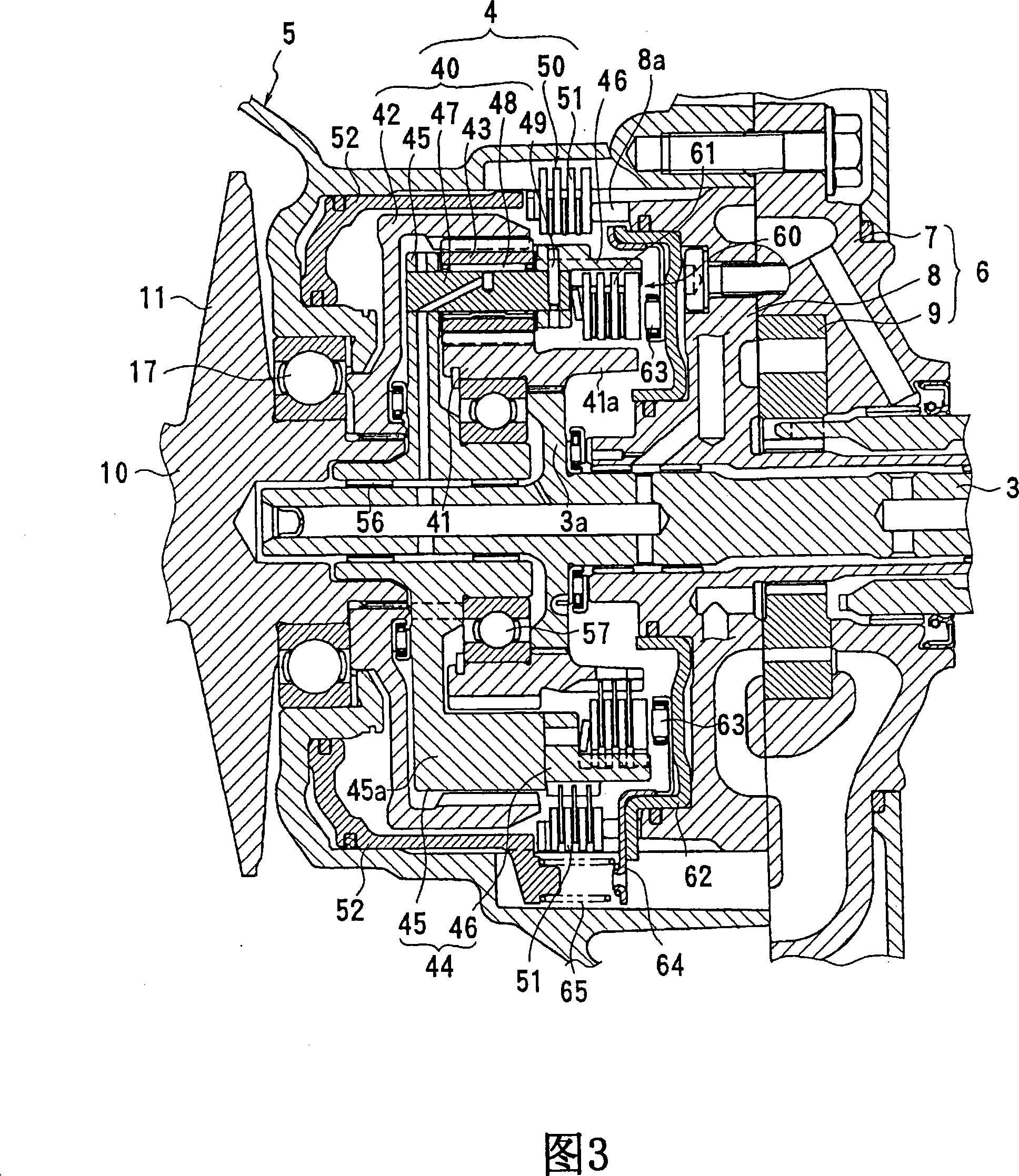
[0031] 1 to 3 show an example of a continuously variable transmission according to the present invention.

[0032]The CVT of this example is a front-front-drive transverse-mounted transmission for an automobile. This transmission basically includes: an input shaft 3 driven by an engine shaft 1 through a torque converter 2; a forward and reverse motion conversion device 4 that changes the rotation of the input shaft 3 forward and backward to transmit the rotation to a drive shaft 10; Drive pulley 11, drive pulley 21, and V-belt 15 wound between the continuously variable transmission device A; differential device 30 that transmits power from driven shaft 20 to output shaft 32; and the like. The input shaft 3 and the drive shaft 10 are arranged on the same axis, and the driven shaft 20 and the output shaft 32 of the differential device 30 are arranged in parallel and non-coaxially with the input shaft 3 . Therefore, this continuously variable transmission is formed of three shaf...

example 2

[0056] A second example of a forward and reverse motion conversion device according to the invention is shown in FIG. 6 . The same parts in FIG. 6 as those of the first example are denoted by the same reference numerals, and repeated description thereof will be omitted. This forward and reverse motion conversion device 4 ′ includes a double planetary gear type planetary gear mechanism 40 ′, a reverse rotation brake 50 and a direct coupling clutch 60 . Two types of planetary gears 43A and 43B are supported by the carrier 44 of the planetary gear mechanism 40'. One planetary gear 43A meshes with the ring gear 42 and the planetary gear 43B, and the other planetary gear 43B meshes with the planetary gear 43A and the sun gear 41 . The sun gear 41 is coupled with the input shaft 3 , and the planet carrier 44 is coupled with the drive shaft 10 . A reverse rotation brake 50 is provided between the ring gear 42 and the transmission housing 5 , and an operating piston 52 that operates...


PUM


Abstract

A continuously variable transmission, a drive device, and a method of controlling the drive device. The continuously variable transmission comprises a belt type continuously variable transmission (A) and a forward / backward movement changeover device (4) having a planetary gear mechanism (40), a reversing brake (50), and a direct-coupled clutch (60) to perform forward / backward movement changeover operation by selectively coupling the reversing brake to the direct-coupled clutch. The operating piston (62) of the direct-coupled clutch is disposed in a stationary cylinder (8) fixed to a transmission case, and the axial pressure of the operating piston is transmitted to the transmission case (5a) through a bearing (16) rotatably supporting the drive side pulley shaft (10) of the continuously variable transmission. Also, the transmission comprises a hydraulic pressure regulating means (SLU72) controlling a supply pressure to the direct-coupled clutch (60) to such a least hydraulic pressure that does not cause slippage on the direct-coupled clutch according to a variation in input torque.

Description

technical field [0001] The present invention relates to a continuously variable transmission, and more particularly, to a continuously variable transmission including a belt-type continuously variable transmission device and a forward and reverse motion converting device having a planetary gear mechanism, a reverse rotation brake and a direct coupling A clutch, the forward and reverse motion converting device, selectively engages a counter-rotating brake and a direct coupling clutch for change in forward and reverse motion. [0002] The present invention also relates to a driving device and a control method thereof. Background technique [0003] A continuously variable transmission including a planetary gear mechanism as a forward and reverse motion conversion device, a direct coupling clutch, and a reverse rotation brake is disclosed in Patent Document 1. FIG. 7 shows a clutch regulator valve used for the clutch pressure control shown in Patent Document 1. As shown in FIG....

Claims


Application Information

Patent Timeline
Patent Type & Authority Applications(China)
IPC IPC(8): F16H61/00F16H37/02F16H57/02F16H59/14F16H57/021F16H57/035
CPCF16H37/022F16H2061/6608F16H61/66259F16H2037/026F16H37/02F16H57/02F16H59/14F16H61/00
Inventor 岛本雅夫久保了一
Owner DAIHATSU MOTOR CO LTD
Learn More