Driving system of loudspeaker
A driving system and loudspeaker technology, applied in the direction of sensors, electrical components, etc., to achieve the effect of improving high-frequency playback, reducing asymmetry, and reducing nonlinearity
- Summary
- Abstract
- Description
- Claims
- Application Information
AI Technical Summary
Problems solved by technology
Method used
Image

Examples
Embodiment 1
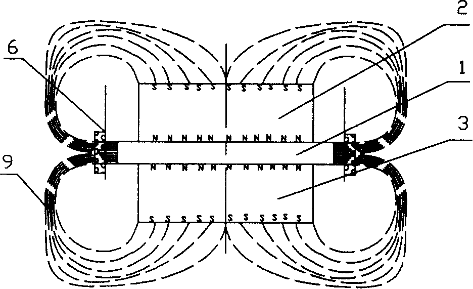
[0027] The present embodiment is a cone loudspeaker, and the structure of its drive system is as follows: Figure 6 shown.
[0028] The loudspeaker is equipped with a 35mm diameter voice coil 6 on a 170mm diameter cone 7. The upper magnet 2, the magnetic pole plate 1, the lower magnet 3 and the iron plate 4 form a magnetic circuit without a magnetic gap. The upper and lower magnets The magnetic poles with the same name are respectively combined with the upper and lower sides of the magnetic pole plate. The bottom is an iron flat plate 4, and the voice coil 6 is set on the side surface of the magnetic pole plate 1. The diameter of the magnetic pole plate 1 is 33.5mm, and the distance between the magnetic pole plate 1 and the inner wall of the voice coil 6 0.75mm, the last magnetic steel 2 is φ (diameter) 30 × 3mm, the lower magnetic steel 3 is φ30 × 15mm, and the iron flat plate 4 below is φ80 × 5mm.
[0029] The magnetic circuit composition principle of the speaker drive syst...
Embodiment 2
[0031] This embodiment is a multi-drive system of a flat panel speaker, such as Figure 7 shown. This system has a square vibrating plate 8, and this vibrating plate is 100 * 100 * 10mm foam plate, is equipped with 4 φ 25mm voice coils 6 at the nodal line position of described vibrating plate, namely the four side center positions of square plate, Each voice coil is equipped with a non-magnetic gap magnetic circuit composed of upper magnetic steel 2, magnetic pole plate 1, lower magnetic steel 3 and iron plate 4. Among them, the magnetic pole plate 1 is φ24mm×4mm, and the inner wall of the voice coil and The average distance between the magnetic pole plates 1 is 0.5mm, and the total thickness of the vibrating plate 8 plus the magnetic circuit is only 25mm, which is much smaller than the traditional design, under the condition that the vertical amplitude is guaranteed to be 8mm. The ferrous plates 4 in the four magnetic circuits are merged into one.
Embodiment 3
[0033] This embodiment is a single voice coil drive system for a flat panel speaker, as shown in FIG. 10 . The system has a square vibrating plate 8, which adopts a φ50mm thick 10mm foam board, and a φ35mm voice coil 6 with a wall thickness of 0.3mm is installed on its pitch circle. The magnetic circuit with a large magnetic gap is located below it, and the magnetic steel 2 is placed on the magnetic circuit. , magnetic pole plate 1, lower magnetic steel 3 and U-shaped iron bowl 5 constitute, the magnetic pole plate 1 diameter is φ 33.5mm, and the inner circle of U-shaped iron bowl 5 is φ 37.5mm. The distance between the inner wall of the voice coil 6 and the magnetic pole plate 1 is 0.75 mm, and the average distance between the outer wall of the voice coil 6 and the inner wall of the U-shaped iron bowl 5 is 1 mm. Such a large distance can effectively avoid "ring rubbing", so there is no need to Fixed core mechanism.
[0034] The magnetic circuit composition principle of the spe...
PUM
 Abstract
Description
Claims
Application Information
 - R&D
- Intellectual Property
- Life Sciences
- Materials
- Tech Scout
- Unparalleled Data Quality
- Higher Quality Content
- 60% Fewer Hallucinations
Browse by: Latest US Patents, China's latest patents, Technical Efficacy Thesaurus, Application Domain, Technology Topic, Popular Technical Reports.
© 2025 PatSnap. All rights reserved.Legal|Privacy policy|Modern Slavery Act Transparency Statement|Sitemap|About US| Contact US: help@patsnap.com