
Board-to-board connector pair

An electrical connector and docking surface technology, applied in the field of board-to-board electrical connectors, can solve problems such as weakening the wiping effect

Inactive Publication Date: 2008-04-16
MOLEX INC
View PDF1 Cites 10 Cited by
  • Summary
  • Abstract
  • Description
  • Claims
  • Application Information

AI Technical Summary

Problems solved by technology

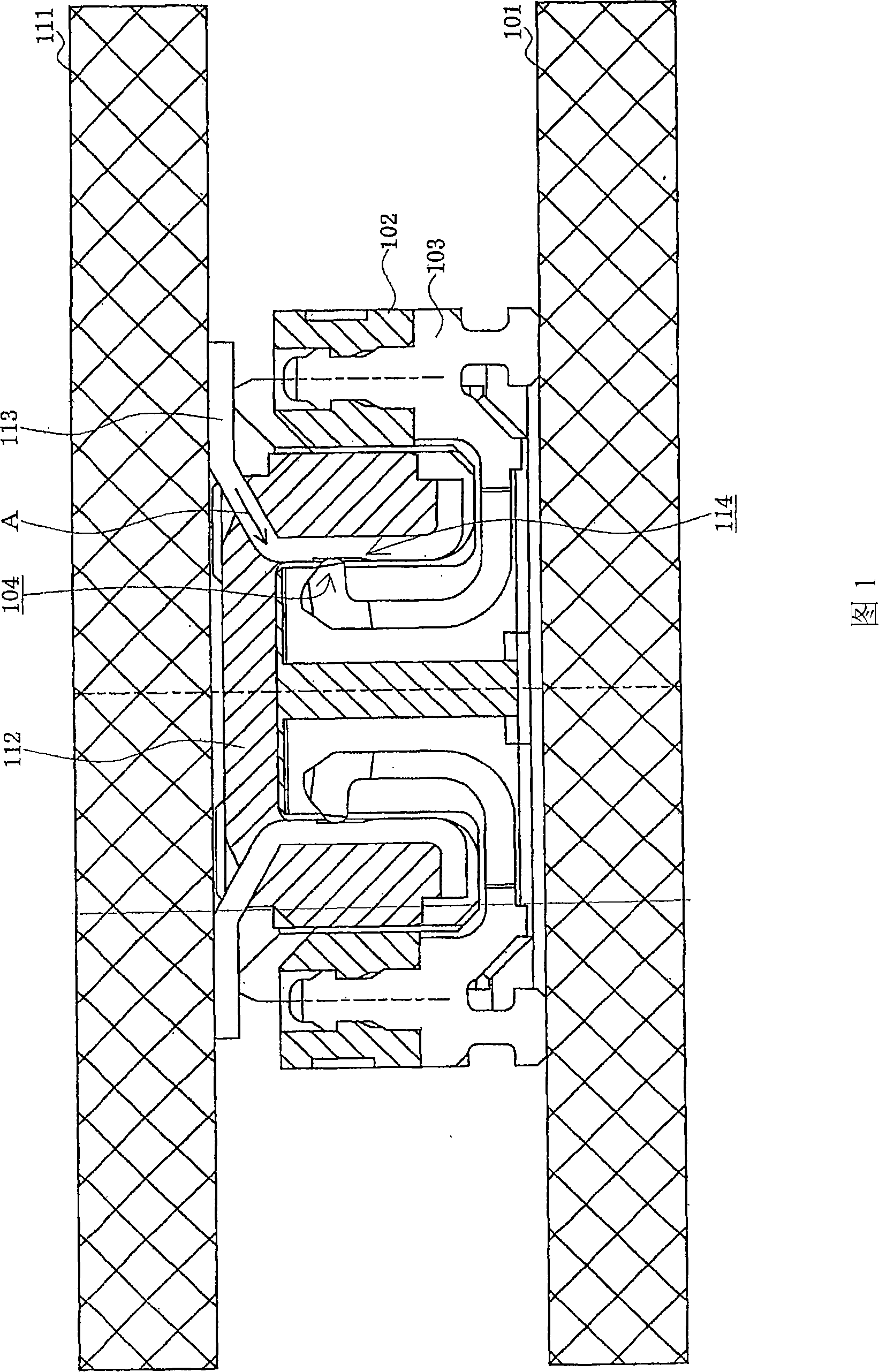
However, when the distal end of the contact portion 104 enters the recess 114, the wiping operation is interrupted thereby weakening the wiping effect.

Method used


Image

  • Board-to-board connector pair
  • Board-to-board connector pair
  • Board-to-board connector pair

Examples


Embodiment Construction

[0018] Embodiments of the present invention will be described in detail later with reference to the accompanying drawings.

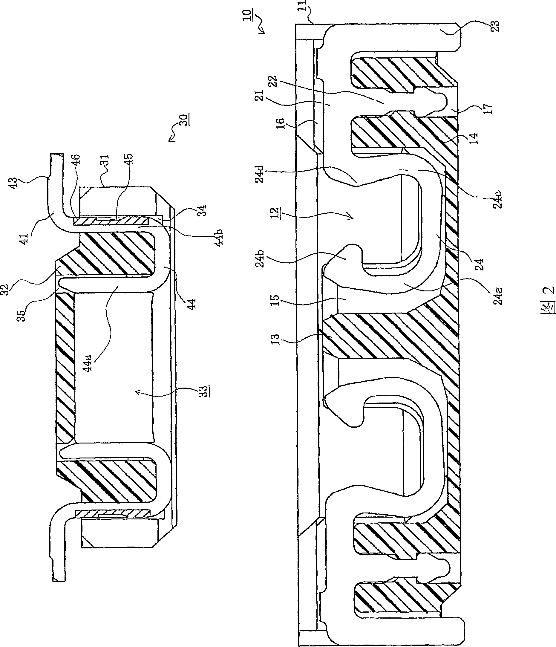
[0019] Referring to FIG. 2 , it shows a first connector 10 and a second connector 30 mated with it. The first connector 10 is one of the paired board-to-board connectors according to the current embodiment of the present invention, and is to be A surface mount type connector mounted on the surface of one circuit board; the second connector 30 is the other of the paired board-to-board connectors according to the current embodiment, and is also to be mounted on the surface of another circuit board surface mount connectors. The paired board-to-board connector (ie, board-to-board connector pair) according to the present embodiment includes a first connector 10 and a second connector 30 , and electrically connects a pair of circuit boards. Although the circuit boards shown in FIG. 1 are printed circuit boards (PCBs), the circuit boards may be of any type, su...


PUM


Abstract

An electrical connector comprises a generally rectangular dielectric housing with a mating face and a mounting face. A plurality of terminal support posts extend in a direction from the mounting face towards the mating face and each support post has oppositely facing first and second sidewalls and a connecting surface. A plurality of terminal receiving cavities are spaced along a longitudinal axis of the housing for receiving terminals therein. A plurality of terminals are provided with each including a solder tail portion and a generally U-shaped contact portion. The solder tail portion is positioned along the mounting face and the contact portion includes a first, distal contact leg, a second, proximal contact leg spaced from and generally parallel to the first contact leg and a connecting portion extending between the first and second contact legs. The first contact leg extends along the first sidewall, the second contact leg extending along the second sidewall, and the connecting portion extending along the connecting surface.

Description

technical field [0001] The present invention relates to electrical connectors, and more particularly to low profile board-to-board electrical connectors. Background technique [0002] Typically, a board-to-board connector pair is used to electrically connect two parallel circuit boards together (see, eg, Japanese Patent Application Laid-Open No. 2004-55463). Such a board-to-board connector pair comprises two connectors which are respectively fixed to and protrude from the mutually facing surfaces of two circuit boards. Referring to FIG. 1 , the first connector 102 includes a plurality of first terminals 103 and is mounted on a first circuit board 101 . The mated second connector 112 includes a plurality of second terminals 113 and is installed on the second circuit board 111 . The first connector 102 and the second connector 112 are butted with each other, thereby connecting the first circuit board 101 and the second circuit board 111 together. [0003] The tail portion o...

Claims


Application Information

Patent Timeline
Patent Type & Authority Applications(China)
IPC IPC(8): H01R12/16H01R12/79
CPCH01R12/716H01R12/57H01R13/41H01R12/73
Inventor 平田智久浅川哲哉
Owner MOLEX INC
Learn More