
Picture element caching method and system in movement compensation process of video decoder

A video decoder and motion compensation technology, applied in the field of video decoding, can solve problems such as inability to reuse, low utilization of reused areas, and irregular shapes of reference frame areas

Inactive Publication Date: 2008-04-16
SHANGHAI JIAO TONG UNIV
View PDF1 Cites 24 Cited by
  • Summary
  • Abstract
  • Description
  • Claims
  • Application Information

AI Technical Summary

Problems solved by technology

This method has the following disadvantages: (1) Due to the uncertainty of the reference frame area reused in motion compensation, this area can only be estimated empirically before decoding a macroblock. This empirical estimation causes two defects: one Because the shape of the reference frame area reused by motion compensation is usually irregular, the above methods all use the method of rectangular approximation, that is, prefetch one or several smaller rectangular areas into the cache space, and use the reused area The rate is not high; the second is that it may appear that the reference frame data pre-read into the cache space is not used by the motion compensation process at all
(2) This method is carried out for each macroblock, and between adjacent macroblocks, a large amount of data will be reused in the motion compensation process, this method cannot reuse these data, so the access to the external memory The amount of reduction effect is not very obvious

Method used


Image

  • Picture element caching method and system in movement compensation process of video decoder
  • Picture element caching method and system in movement compensation process of video decoder
  • Picture element caching method and system in movement compensation process of video decoder

Examples


Embodiment Construction

[0057] Below in conjunction with the accompanying drawings, the embodiments of the present invention are described in detail: the present embodiment is implemented on the premise of the technical solution of the present invention, and provides detailed embodiments and specific operation processes, but the protection scope of the present invention is not limited to the following described embodiment.

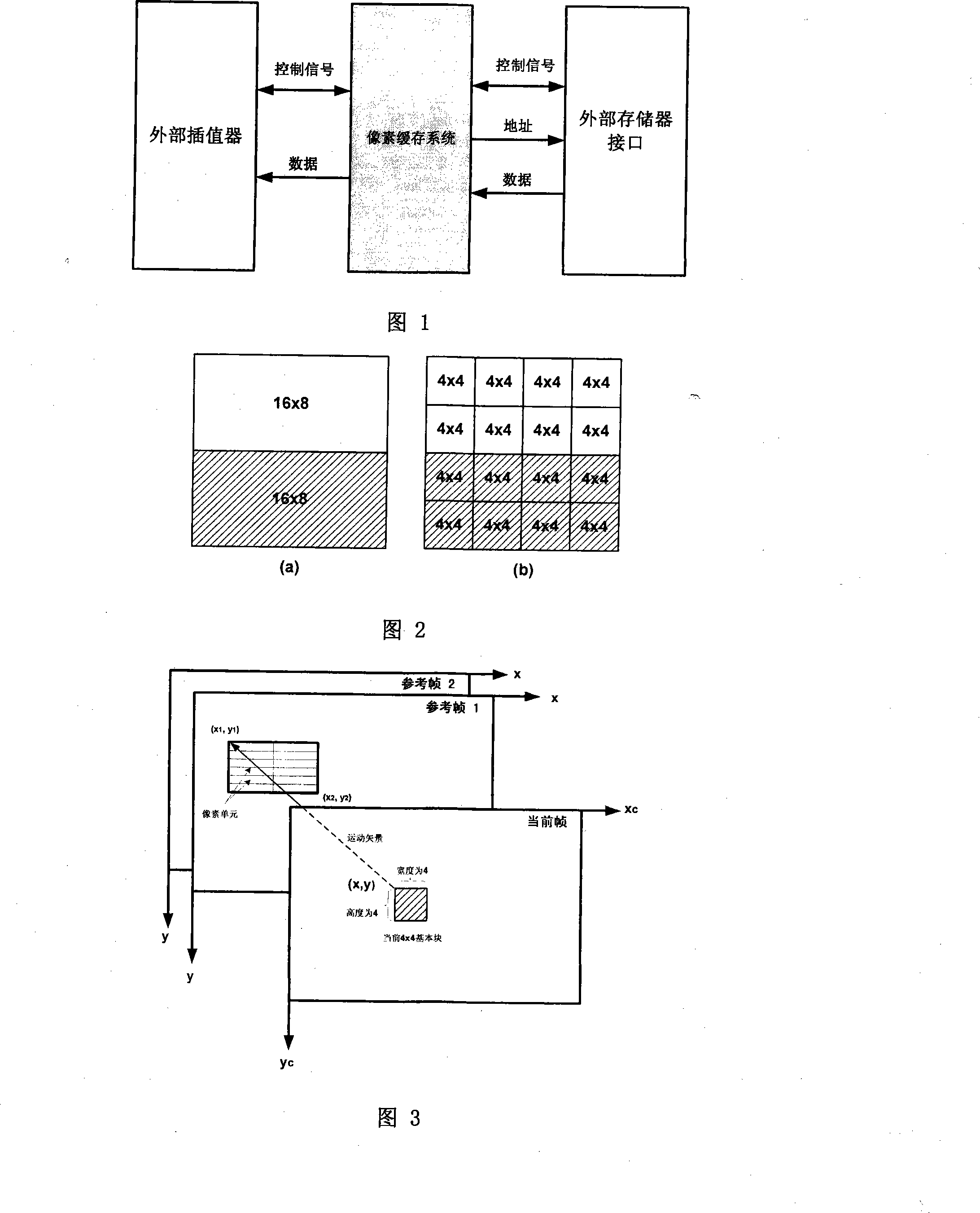
[0058] This embodiment is implemented based on the H.264 protocol, and each macroblock is divided into 16 basic blocks with a size of 4×4 for motion compensation.

[0059] As shown in FIG. 1, it is a schematic diagram of the position of the system in this embodiment in the hardware video decoder. The system in this embodiment is between the external memory interface and the external interpolator, and reads data from the external memory through the external memory interface. When Once the data is ready, an external interpolator is started and provided with data.

[0060] As shown...


PUM


Abstract

An image element cache method and system, which is used in the motion compensation of an audio decoder in the field of audio decoding, includes: step 1. Reading motion compensation parameter information from the parameter memorizer; step 2. Zoning the area of the reference frame where the current basic block of motion compensation needs; step 3. Reading and selecting the image elements that are not in the internal memorizer out of the external memorizer and memorizing them in the internal memorizer; step 4. Reading and selecting out the data in the reference frame image element unit of the reference frame area from the internal memorizer in turn, and sending them together with the current motion vector of the basic block to an external interpolator. The invention system includes: an overall controlling module, a parameter module reading motion compensation, a reference frame area module which the motion compensation need, a judging and replacing module of image element unit, a controlling module of interpolation data output, and a memorizing module of data and label. The invention reduces the bandwidth need for external memorizer, and resolves the bandwidth bottleneck problem of the external memorizer of the audio decoder design.

Description

technical field [0001] The present invention relates to a method and system in the field of video decoding, in particular to a pixel buffering method and system in the motion compensation process of a video decoder. Background technique [0002] Motion compensation is the inverse process of motion estimation, and it is an effective method to reduce temporal redundant information in video sequences. The current mainstream video codec standards, such as MPEG-x series, H26x series and China's AVS standard, all use motion compensation technology, and they only have certain differences in parameter selection. [0003] Since each frame image in a video sequence contains a large amount of data, in the design of a video decoder, the decoded frame is usually stored in an external memory with a large storage capacity and a slow access speed, such as SDRAM (Synchronous Dynamic Random Access Memory) ), some of these frames stored in the external memory will be used as reference frames ...

Claims


Application Information

Patent Timeline
Patent Type & Authority Applications(China)
IPC IPC(8): H04N7/26H04N7/32H04N19/433H04N19/44
CPCG06F12/0875
Inventor 陈先民周大江刘佩林
Owner SHANGHAI JIAO TONG UNIV
Learn More