
Device for illumining multiple fluorescent lamps

A fluorescent lamp and circuit technology, applied in lighting devices, light sources, electric light sources, etc., can solve problems such as failure to significantly improve energy-saving effects, waste of raw materials and precious energy, and power consumption by ballasts, so as to improve lighting quality and increase power. factor, the effect of reducing the total amount of harmonics of the input current

Inactive Publication Date: 2008-04-09
王尺
View PDF0 Cites 1 Cited by
  • Summary
  • Abstract
  • Description
  • Claims
  • Application Information

AI Technical Summary

Problems solved by technology

[0012] According to the above data, the power consumption of electric light source is not only the electric light source itself, but also the ballast is also consuming electric energy.
In addition, most manufacturers engaged in the development and production of lighting technology have invested a lot of manpower, equipment, and funds in the research of using lighting appliances as pure resistive loads, with little success and no obvious improvement in energy saving effect.
[0013] In the prior art, due to the low utilization rate of electric energy for most common electric light sources and the low quality of lighting, raw materials and precious energy are wasted

Method used


Image

  • Device for illumining multiple fluorescent lamps
  • Device for illumining multiple fluorescent lamps

Examples


Embodiment Construction

[0033] Below in conjunction with accompanying drawing and specific embodiment the present invention is described in further detail:

[0034] The product VIcosθ of current and voltage is called active power (in W), and the product VI of current and voltage is called apparent power (in VA). The ratio of active power to apparent power is called power factor PF (Power Factor).

[0035] PF=W / VA=VAcosθ / VA=cosθ

[0036] Regardless of active power or reactive power, it is supplied by the generator through the transmission network and distribution lines, but the watt-hour meter, that is, the kWh meter, calculates only the active power part. Active power includes the voltage drop and line loss of reactive current in the line. Total current I = active current I 1 + reactive current I 2 , if the power factor of the load can be effectively reduced and the reactive current I 2 To turn on the lights can achieve the purpose of energy saving. The capacitive load can provide the reactive ...


PUM


Abstract

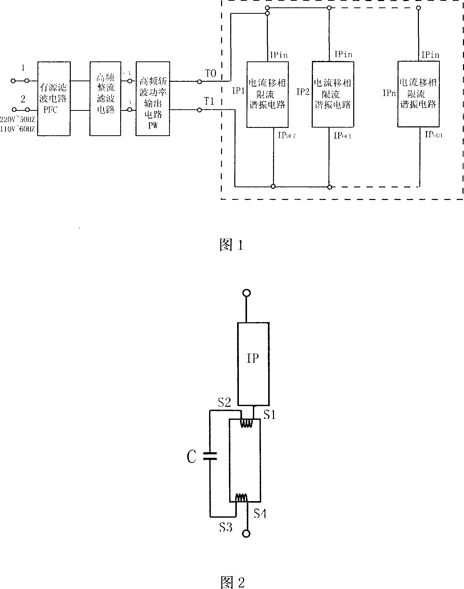
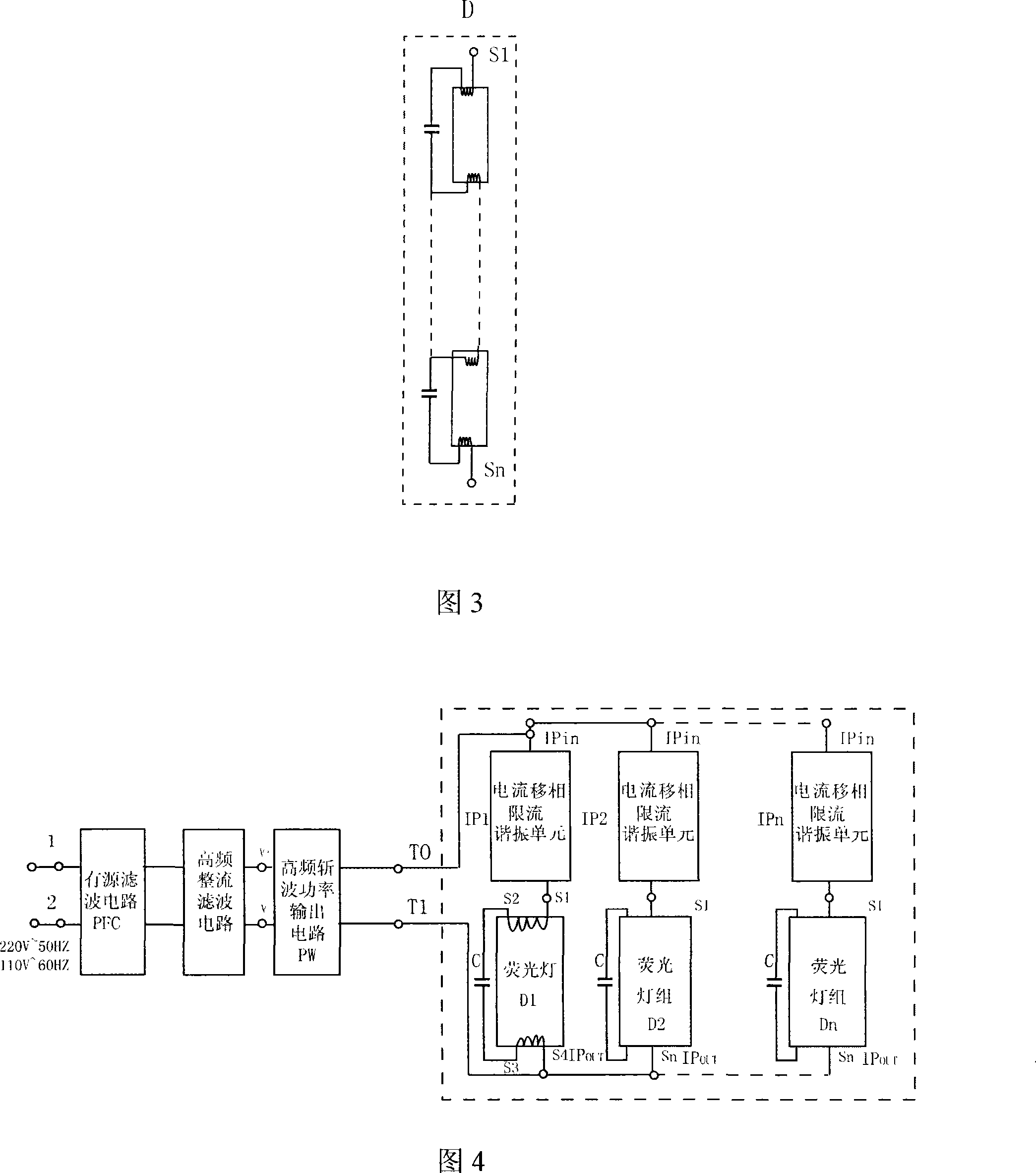
The invention discloses a device of lighting up a plurality of fluorescent lamps, which includes an active filter circuit, a high frequency rectification filter circuit, a high frequency chopper power output circuit, and a current phase shift, current limit and resonance circuit, which is serially connected with a fluorescent tube set. Main supply is output to the high frequency chopper power output circuit through the active filter circuit and the high frequency rectification filter circuit; the high frequency chopper power output circuit is powered by two or more than two current phase shift, current limit and resonance circuits in parallel connected with an output circuit. The invention has the advantages that the adoption of a high frequency switch power supply and the current phase shift, current limit and resonance circuit can facilitate an electric light source to obtain higher photoelectric conversion efficiency on the premise of using lower power, light up a plurality of the fluorescent lamps simultaneously, obviously improve lighting quality and power factor although cancelling a plurality of ballasts, starters or a plurality of electronic ballasts, in order to save raw material and energy.

Description

technical field [0001] The invention relates to the technical field of electric light source lighting, in particular to a device capable of lighting multiple fluorescent lamps. Background technique [0002] The traditional way to light up the electric light source is to determine the input mains voltage, lamp voltage, lamp current, and use inductors, capacitors, resistors or electronic ballasts to limit the current, step down, boost and other methods to ensure the electric light source. startup and normal operation. [0003] At present, household electric light sources can be basically divided into three types: ordinary lamps (tungsten lamps), halogen lamps and fluorescent lamps; fluorescent lamps are mainly composed of lamp tubes, starters, and ballasts. The working principle of fluorescent lamp tubes is: switch on After the power supply, the voltage is applied between the two poles of the starter, so that the neon gas discharges and emits a glow. The heat generated by the...

Claims


Application Information

Patent Timeline
Patent Type & Authority Applications(China)
IPC IPC(8): H05B41/298H05B41/36
CPCH05B41/2822
Inventor 王尺
Owner 王尺
Learn More