Down hole physical upgrading of heavy crude oils by selective energy absorption

A crude oil, electromagnetic energy technology, applied in wellbore/well components, isolation devices, production fluids, etc., can solve the problem that the visbreaking process cannot work in situ

Inactive Publication Date: 2008-03-12
KSN ENERGIES
View PDF1 Cites 4 Cited by
  • Summary
  • Abstract
  • Description
  • Claims
  • Application Information

AI Technical Summary

Problems solved by technology

However, as currently applied, the visbreaking process cannot act on the oil in situ

Method used


Image

  • Down hole physical upgrading of heavy crude oils by selective energy absorption
  • Down hole physical upgrading of heavy crude oils by selective energy absorption
  • Down hole physical upgrading of heavy crude oils by selective energy absorption

Examples


Embodiment Construction

[0018] Electromagnetic energy can be applied in situ to heavy crude oil using various forms of downhole electromagnetic structures. The appropriate configuration for any particular application will depend on factors including depth, uniformity of heat, and minimization of unsaturated hydrocarbon generation and coking.

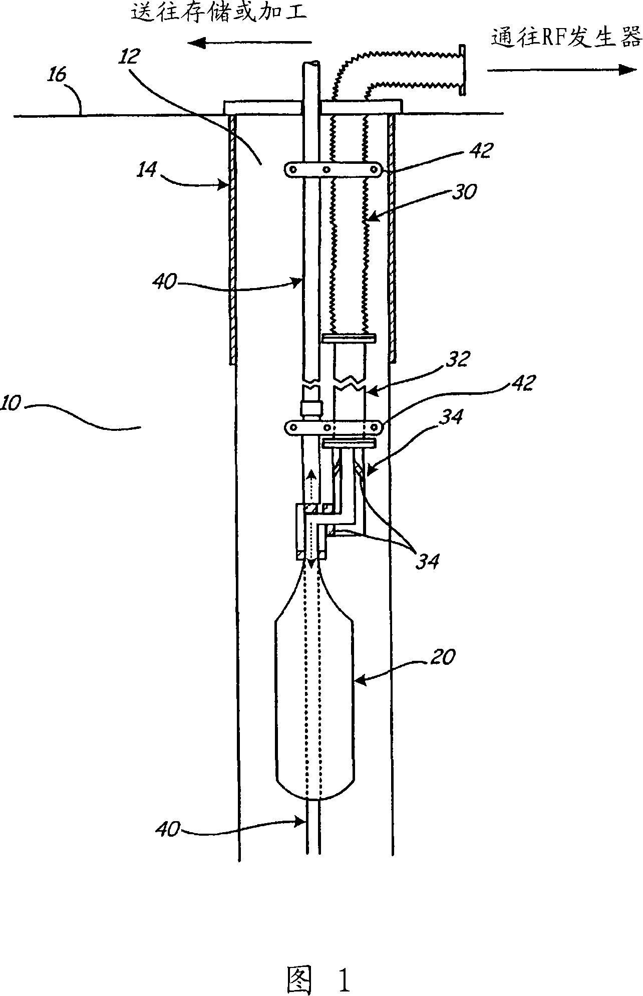
[0019] Figure 1 is a perspective view of a single borehole radial applicator. Applicator system 10 is placed within wellbore 12 . Wellbore 12 is supported by casing 14 . Electromagnetic energy is then applied to the heavy crude oil near the wellbore 12 using the applicator system 10 .

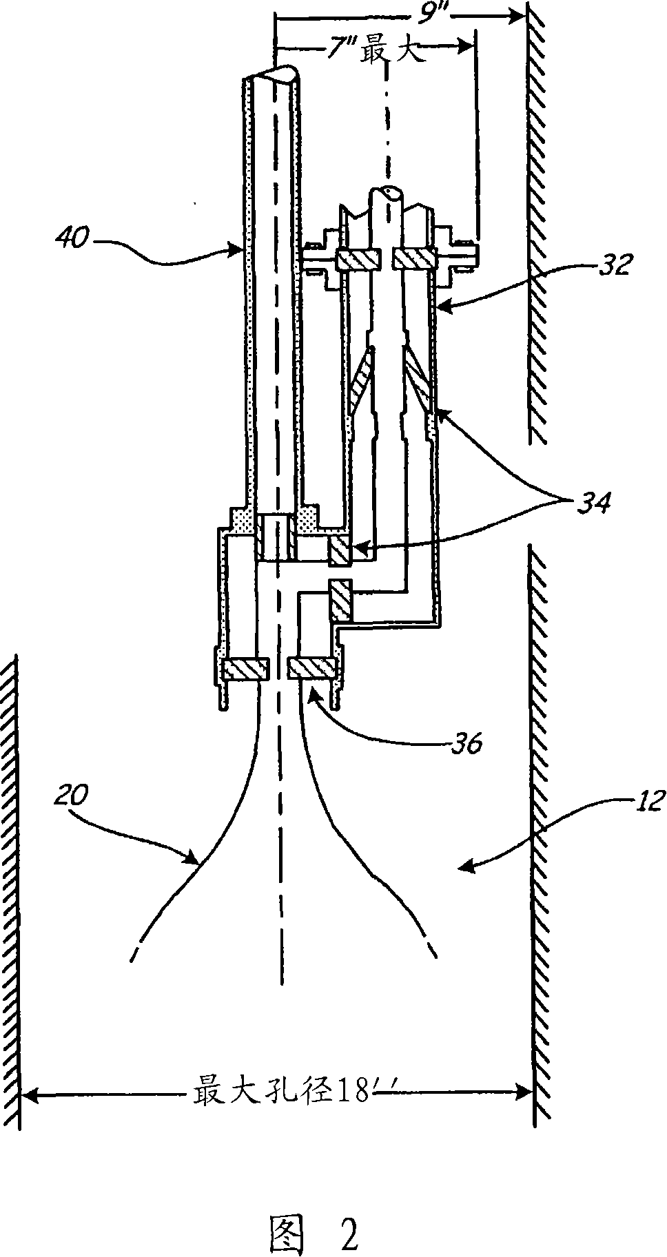
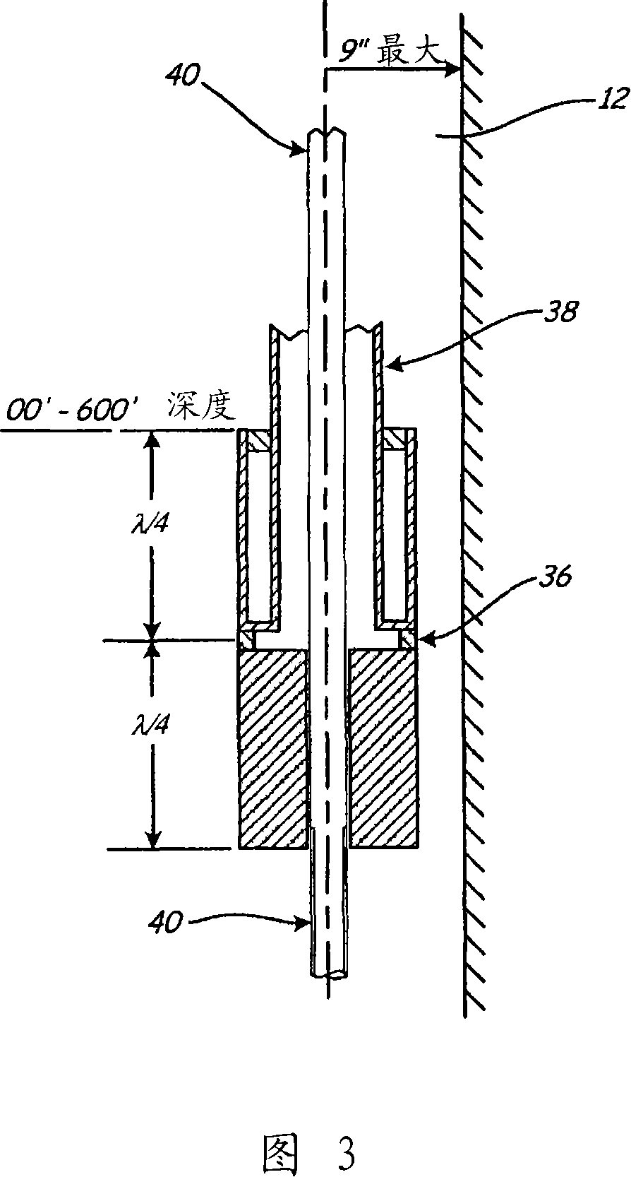
[0020] Applicator structure 20 is a transmission line retort. For reference, a typical applicator 20 is approximately 70 feet in length. In a typical configuration, applicator 20 may be placed in borehole 12 100-600 feet underground. Radio frequency ("RF") energy is provided to applicator 20 using an RF generator (not shown). The RF generator is connected to the applicator...


PUM


Abstract

The present invention utilizes the ability of electromagnetic energy at the appropriate frequency to selectively deposit thermal energy in the heavy oil for precise control of cracking temperature throughout a given volume of material. Selective electromagnetic energy absorption in the heavy crude oil provides energy efficient transfer of heat at the molecular level and thereby insures precise temperature control throughout the treatment volume. This allows for optimization of the visbreaking process using electromagnetic energy.

Description

technical field [0001] The present invention generally relates to the use of electromagnetic energy to subject heavy crude oil to mild thermal cracking conditions, thereby reducing the viscosity, pour point and specific gravity of the oil, making it easier to recover and manipulate. More particularly, the present invention relates to methods of applying electromagnetic energy to heavy oil in a reservoir to upgrade and facilitate recovery in situ. The invention also relates to a system for in situ application of electromagnetic energy to heavy oil. Background technique [0002] Heavy crude oil has some problems in extraction and production. Crude oils with low API gravity and crude oils with high pour points have production problems both in and out of the reservoir. Extracting and refining this oil is more difficult and expensive. In particular, pumping heavy crude oil or moving it through pipelines is difficult. [0003] Today, various methods are used to ameliorate the ...

Claims


Application Information

Patent Timeline
Patent Type & Authority Applications(China)
IPC IPC(8): E21B43/24E21B36/04
CPCE21B43/2401E21B36/04
Inventor 雷蒙德·S·凯斯维克
Owner KSN ENERGIES
Why Eureka
Try Eureka