
Inflator

An inflator and gas technology, applied in the direction of gas generating devices, vehicle safety arrangements, pedestrian/passenger safety arrangements, etc., can solve the problems of longer release time, weakening, and difficulty in maintaining the first impact and inflation time of the airbag at the same time, Achieve the effect of compact cylindrical frame and enhance the first impact

Inactive Publication Date: 2008-03-12
TAKATA CORPORATION
View PDF1 Cites 4 Cited by
  • Summary
  • Abstract
  • Description
  • Claims
  • Application Information

AI Technical Summary

Problems solved by technology

[0004] However, according to the above-mentioned prior art, since the gas discharge hole is directly provided on the opposite side of the main body containing the gunpowder in the container containing the compressed gas, the aperture diameter of the discharge hole is set so that the airbag passes through the first powder within 50 milliseconds. When expanding, the release time of the compressed gas generated by the second propellant becomes shorter; when the diameter of the discharge hole is reduced to prolong the release time of the compressed gas generated by the second propellant, the first impact generated by the first propellant (initial rapid deployment of the airbag) weakening
Therefore, there is a problem that it is difficult to maintain the first impact and inflation time of the airbag at the same time

Method used


Image

  • Inflator
  • Inflator
  • Inflator

Examples


Embodiment Construction

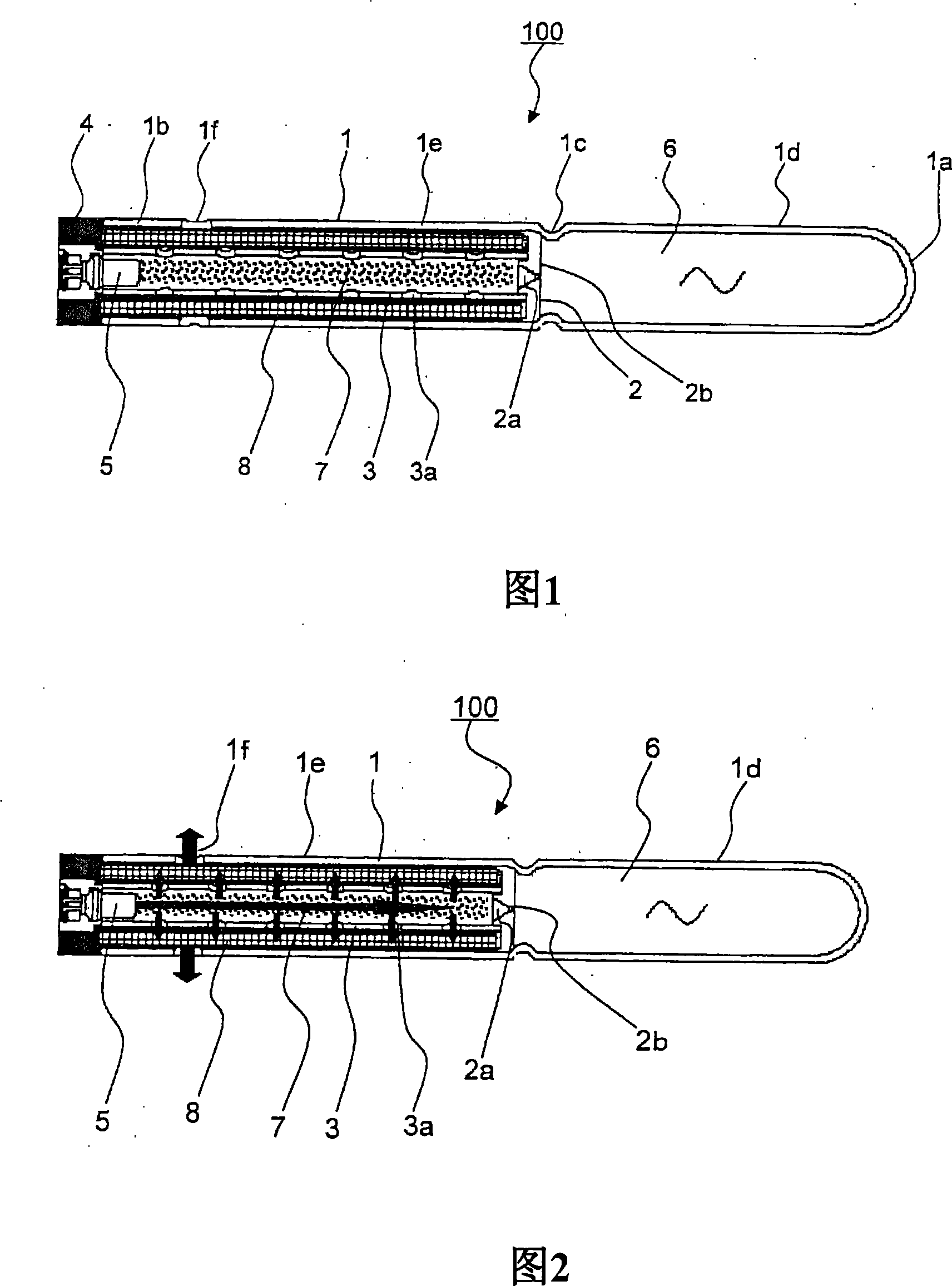
[0021] Hereinafter, embodiments of the present invention will be described with reference to the drawings. FIG. 1 is a cross-sectional view showing an embodiment of the inflator of the present invention.

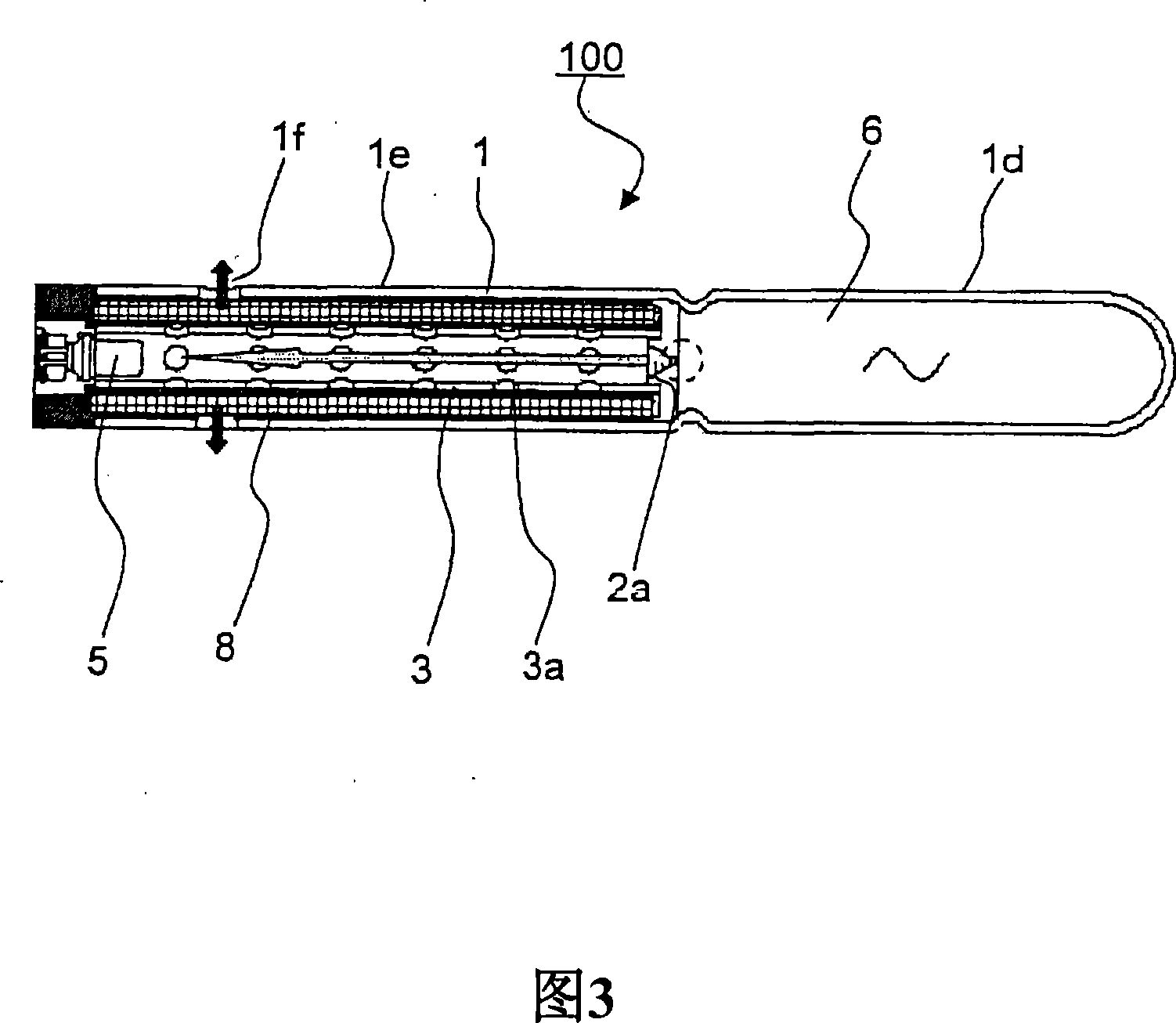
[0022] As shown in FIG. 1 , the inflator 100 of the present embodiment is suitable for an inflator used in, for example, a curtain air bag (not shown) that can be deployed on the side of a vehicle compartment. The frame is a cylindrical frame 1 similar to a test tube, with a hemispherical bottom 1a at one end, an opening 1b at the other end, and a narrow portion 1c in the middle.

[0023] An orifice plate 2 serving as a flow adjustment member inserted from the side of the opening 1 b is airtightly fixed to the narrow portion 1 c of the cylindrical frame 1 . At the center of the orifice plate 2, an orifice 2a is formed as an adjustment hole for generating airflow resistance. The orifice 2a has a diameter of about 1 mm, and is closed by a thin metal plate 2b having a thickne...


PUM


Abstract

The inflator satisfies both of the strength of a first impact of the airbag and a keeping operation for a duration of expansion of the airbag. The inflator 100 supplies gas into an airbag mounted on a motor vehicle and deploys the same. A first chamber 1e where a gas-blowing outlet 1f is provided and a gas-generating agent 7 generating the gas while being ignited by means of an initiator 5 is encapsulated. A filter 8 is arranged between the gas-blowing outlet 1f of the first chamber 1e and the gas-generating agent 7, absorbs heat of combustion of the gas-generating agent 7, and captures a residue thereof. A second chamber 1d is partitioned from the first chamber 1 e with a flow amount control member 2 where the compressed gas 6 is encapsulated. A blocking member 2b of a control hole 2a of the flow amount control member 2 is provided which opens the control hole 2a by being ruptured or removed by expanding pressure of the gas-generating agent 7 .

Description

technical field [0001] The present invention relates to an inflator (gas generator) for inflating and deploying an airbag such as a curtain airbag that is equipped on a vehicle (automobile) to constrain an occupant when the vehicle rolls over (rollover). Background technique [0002] Conventionally, there is a gas generator (inflator) that inflates an air bag to ensure vehicle safety, and includes a main body having an ignition unit (initiator) and a container (gas chamber) that is connected to the main body and accommodates compressed gas , the container having a discharge hole initially closed, wherein said body has: a first powder capable of combining with a prescribed amount of gas contained in the container to generate a prescribed amount capable of inflating the airbag within a period of 50 milliseconds and the second gunpowder, which can produce enough gas to maintain the airbag in the inflated state during the few seconds after the first gunpowder burns (for example,...

Claims


Application Information

Patent Timeline
Patent Type & Authority Applications(China)
IPC IPC(8): B60R21/264B01J7/00B60R21/20B60R21/232B60R21/26
CPCB60R21/268B60R21/264
Inventor 矢野完侍
Owner TAKATA CORPORATION
Learn More