
Pulse laser sediment method

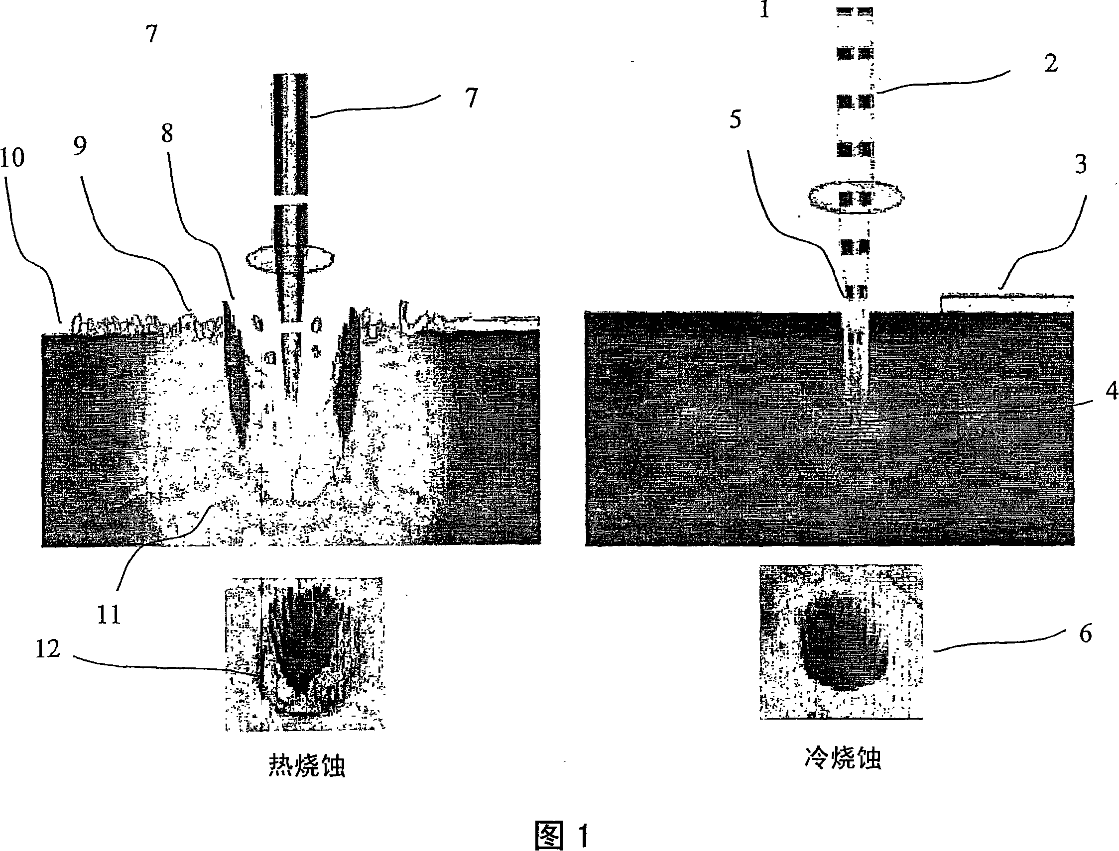
A laser, laser ablation technology, used in optics, optical components, coatings, etc., can solve problems such as low operating speed and low operating speed

Inactive Publication Date: 2008-02-20
比克顿有限公司
View PDF1 Cites 9 Cited by
  • Summary
  • Abstract
  • Description
  • Claims
  • Application Information

AI Technical Summary

Problems solved by technology

However, the second pulsed laser for cold ablation is only capable of pulse frequencies measured in kilohertz, operating at slower speeds than, for example, picosecond lasers in many cutting applications

Method used


Image

  • Pulse laser sediment method
  • Pulse laser sediment method
  • Pulse laser sediment method

Examples


example

[0039] The methods and products of the invention are described below without limiting the invention to the examples given. The coating was produced using two X-lase 10W picosecond lasers manufactured by the company Corelase Oy and an X-lase 10W picosecond laser manufactured by the company Corelase Oy. Pulse energy refers to pulse energy incident on an area of ​​1 square centimeter, which is focused on an area of ​​desired size using optics.

example 1

[0041] In this example, a polycarbonate plate was coated with a diamond coating (sintered carbon). The laser device has the following performance parameters:

[0042] Power: 10W

[0043] Repetition frequency: 4MHz

[0044] Pulse energy: 2.5μJ

[0045] Pulse period: 20ps

[0046] Distance between target and substrate: 35mm

[0047] Vacuum level: 10 -7

[0048] The polycarbonate plate was thus coated with a DLC coating with a thickness of about 200 nm.

example 2

[0050] In this example, bone screws made of roster are covered with a titanium coating. The laser device has the following performance parameters and the coating is produced from ablation sintered carbon:

[0051] Power: 10W

[0052] Repetition frequency: 4MHz

[0053] Pulse energy: 2.5μJ

[0054] Pulse period: 20ps

[0055] Distance between target and substrate: 37mm

[0056] Vacuum level: 10 -8

[0057] The diamond coating (DLC) thus produced has a thickness of about 100 nm.


PUM

PropertyMeasurementUnit
Pulse energyaaaaaaaaaa
Thicknessaaaaaaaaaa
Thicknessaaaaaaaaaa

Abstract

The invention relates to a method for coating a body of metal, glass, rock or plastic, in which the body is coated by laser ablation, with the body shifted in a material plasma fan ablated from a moving target in order to achieve a coating having as regular quality as possible. The invention also relates to the product produced by the method.

Description

technical field [0001] The invention relates to a method for pulsed laser ablation deposition (PLD - pulsed laser deposition) and to a method for producing a product with optimal surface quality by ablation of a moving target against a moving substrate for coating. Background technique [0002] This laser technology has advanced considerably in recent years, and at present, laser systems based on semiconductor fibers can be produced with reasonable efficiency, for example for cold ablation. Such lasers intended for cold ablation include picosecond and femtosecond lasers. For example, in the case of picosecond lasers, the cold ablation range means pulse lengths with periods of 100 picoseconds or less. Picosecond lasers differ from femtosecond lasers both for their pulse period and their repetition rate, with the latest commercial picosecond lasers having repetition rates in the 1-4 MHz range, whereas femtosecond lasers operate only at repetition rates measured in kilohertz. ...

Claims


Application Information

Patent Timeline
IPC IPC(8): C23C14/28C03C17/00C04B41/45A61L27/30B29C45/56C23CG02B1/04G02B1/10
Inventor 杰瑞·鲁图
Owner 比克顿有限公司
Learn More