
Road conditions video camera marking method under traffic monitoring surroundings

A camera calibration and road condition technology, which is applied in the field of intelligent transportation, can solve the problems of reducing the scope of application of the calibration algorithm and difficult to meet the high-precision calibration requirements of the camera, and achieve the effect of improving robustness and simplifying the calibration process

Inactive Publication Date: 2008-02-06
NANJING UNIV
View PDF0 Cites 40 Cited by
  • Summary
  • Abstract
  • Description
  • Claims
  • Application Information

AI Technical Summary

Problems solved by technology

This type of method is simple to implement and has linear time computational complexity. However, when establishing a 3D mapping model, it needs to solidify some internal parameters of the camera model (principal point coordinates and distortion parameters), which reduces the scope of application of the calibration algorithm and is difficult to meet the requirements of high-resolution cameras. Accuracy Calibration Requirements

Method used


Image

  • Road conditions video camera marking method under traffic monitoring surroundings
  • Road conditions video camera marking method under traffic monitoring surroundings
  • Road conditions video camera marking method under traffic monitoring surroundings

Examples


Embodiment Construction

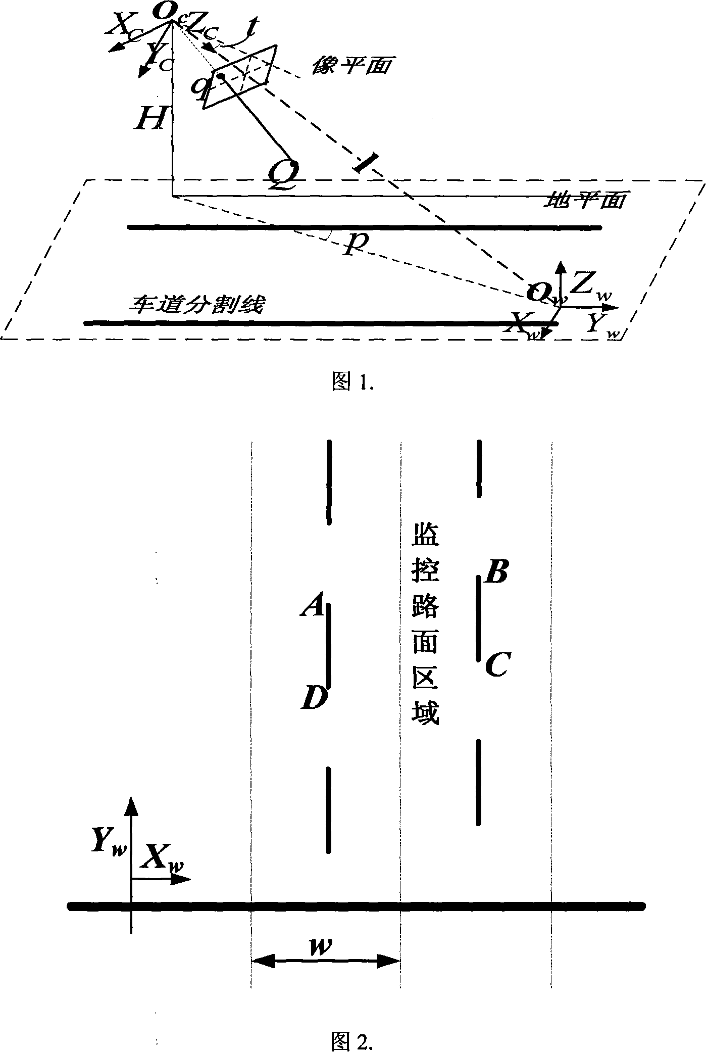
[0039] (1) Visual model description and related coordinate system establishment: Aiming at the performance requirements of the monitoring system, the classic Tsai transmission projection model is used, and a new visual model is proposed according to the characteristics of road imaging, as shown in Figure 1.

[0040] Three coordinate systems are defined in the figure, among which the ground coordinate system X w -Y w -Z wand the camera coordinate system X c -Y c -Z c Used to represent three-dimensional space; image plane coordinate system X f -Y f Used to characterize the imaging plane. Establish a world coordinate system whose origin is the intersection of the camera optical axis and the ground. Y w The positive axis points forward along the direction of the road surface, X w The positive axis points horizontally to the right, Z w The positive axis is perpendicular to the ground and the direction is upward. Establish the camera coordinate system, the origin is the p...


PUM


Abstract

A road condition video camera demarcating method under the traffic monitoring condition includes the following demarcating steps: (1) visual model describing and relevant coordinate system creating: according to the requirement of the monitoring system performance, a classical Tsai transmission projection model is used for reference, and according to the feature of the road condition imaging, a new visual model is presented after conducting corresponding amendment on the classical Tsai transmission projection model, and three kinds of coordinates are established. (2) demarcating the main point of a video camera and the extension factor: the image monitoring light stream is used as the demarcating basic element; by the extension movement of the video camera, a reference frame forecast image and the difference value of the light stream field in a real time frame sampling image are used as the restriction, a constraint equation is established by adopting the least square method, the main point coordinate of the video camera and the actual magnification coefficient of the video camera can be distinguished by the powell direction family method. (3) Demarcated object selecting and parameter linearity evaluating. (4) Accuracy making on the internal and external parameters of the video camera: according to all the angle points of the monitored image and the corresponding world coordinate point, the Levenberg-Marguardt optimization algorithm is adopted to make accuracy on the video camera model parameter, and then the video camera demarcating is finished.

Description

technical field [0001] The invention belongs to the technical field of intelligent transportation, in particular to a method for calibrating a road condition camera in a traffic monitoring environment, and is mainly used for the precise calibration of a pan-tilt camera in a traffic monitoring environment. Background technique [0002] Applying TV video technology, communication and network technology, pattern recognition technology, computer vision technology and other technologies to develop existing traffic video monitoring technology and realize automatic collection and analysis of traffic information flow is a research with broad application prospects in the field of intelligent transportation technology direction. Its goal is to use computer vision technology to detect, locate, identify and track the movement of vehicles, pedestrians and other traffic targets by analyzing the sequence of road monitoring images, and to analyze and judge the traffic behavior of the detect...

Claims


Application Information

Patent Timeline
IPC IPC(8): G06T7/00G08G1/01H04N5/225
Inventor 陈启美李勃郭凡董蓉
Owner NANJING UNIV
Learn More