Double-wire feeding arc welding method and multi-layer surfacing method
An arc welding method, welding method technology, applied in the direction of arc welding equipment, welding equipment, manufacturing tools, etc., can solve the problems of insufficient undercut filling and weakened surface tension, etc., achieve efficient reciprocating welding, suppress unevenness, Suppresses undercut and underfill effects
- Summary
- Abstract
- Description
- Claims
- Application Information
AI Technical Summary
Problems solved by technology
Method used
Image
Examples
Embodiment approach 1
[0034] Hereinafter, Embodiment 1 of the present invention will be described with reference to the drawings.
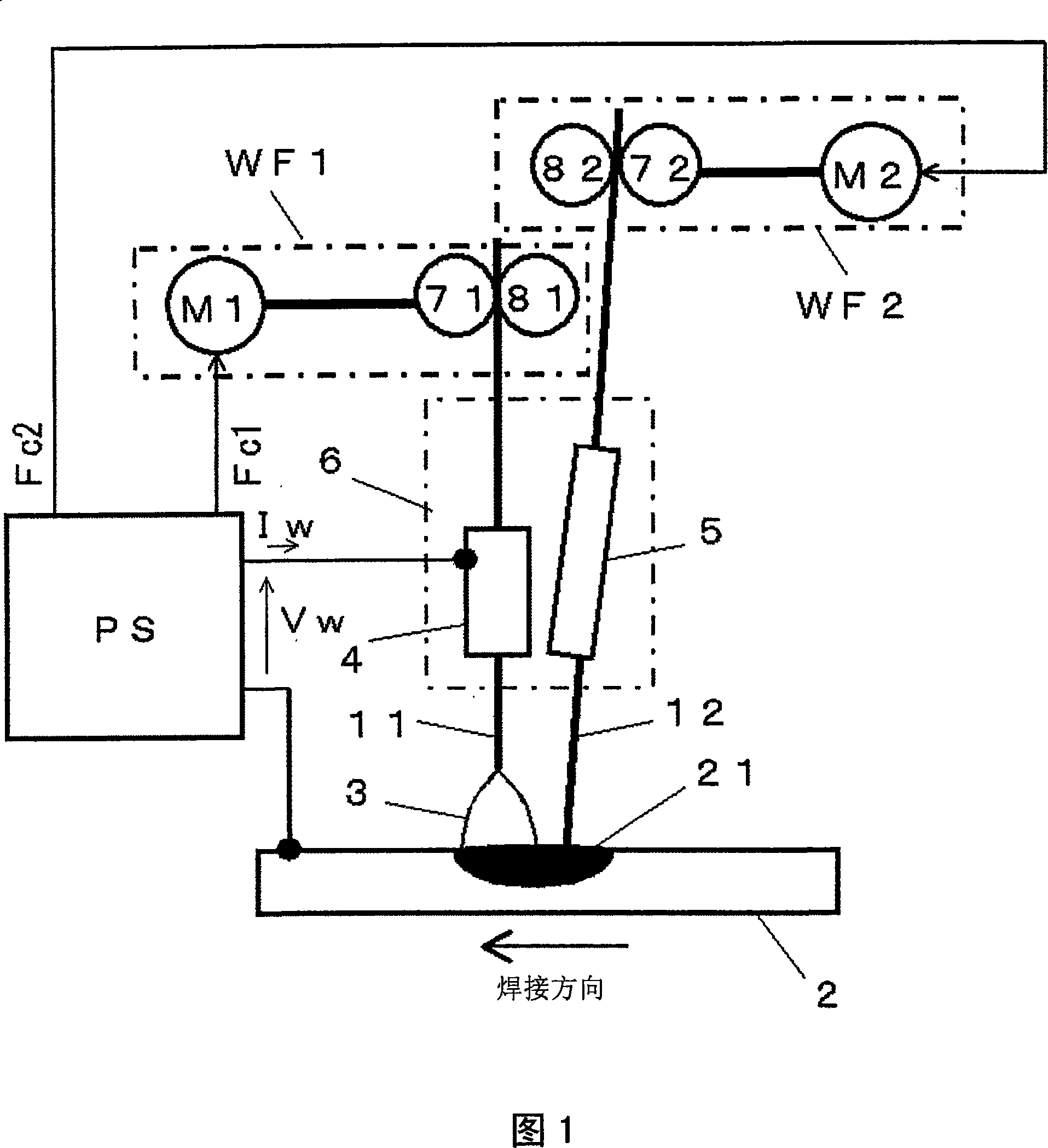
[0035] FIG. 1 is a configuration diagram of a double wire feed arc welding device according to Embodiment 1 of the present invention. This figure shows the case where the first welding wire 11 is used as the preceding welding wire, and the second welding wire 12 is used as the following welding wire. The following description will be made with reference to this figure.
[0036] The welding power supply PS outputs the welding voltage Vw and the welding current Iw between the power supply core 4 and the base metal 2 in order to generate the arc 3 for the first welding wire 11 (leading welding wire), and outputs to control the rotation of the first feeding motor M1 The first feed control signal Fc1 and the second feed control signal Fc2 for controlling the rotation of the second feed motor M2.
[0037] The first feeding motor M1 rotates and drives the first feeding roll...
Embodiment approach 2
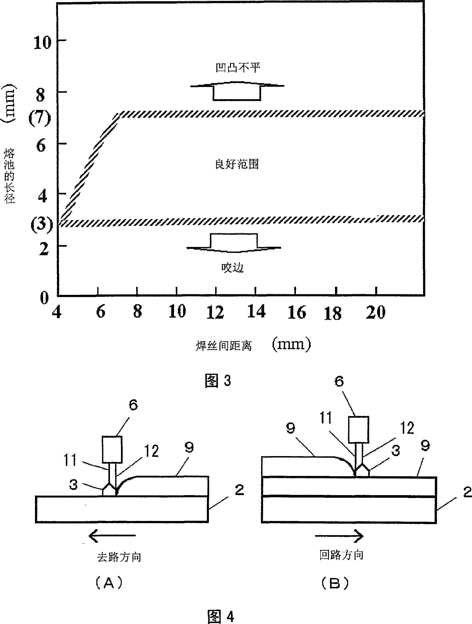
[0051] FIG. 4 is a diagram showing a multi-layer build-up welding method using the above-mentioned double wire feed arc welding method according to Embodiment 2 of the present invention. The first welding wire 11 and the second welding wire 12 are fed from one welding torch 6, and the welding torch 6 is reciprocated to perform welding of each layer. The figure (A) shows the time of moving the welding torch 6 in the forward direction and welding, and the figure (B) shows the time of moving the welding torch 6 in the direction of the return and welding. Hereinafter, description will be made with reference to this figure.
[0052] As shown in the figure (A), when welding in the forward direction, the first welding wire 11 is used as the leading welding wire, and the second welding wire 12 is used as the following welding wire. Therefore, the arc 3 is generated between the first welding wire 11 as the preceding welding wire and the base material 2 to perform molten electrode arc ...
Embodiment approach 3
[0060] Since construction machinery, keels / bridges, etc. are welded structures with thick plates, the amount of deposited metal at the welded part needs to be large, and the welding construction takes a long time. Therefore, recently, welding work has often been carried out with a welded joint of a narrow cut in which the cut width becomes narrow and the cut depth becomes deep. In such narrow-gap welding, as described above, when a material that reduces the viscosity of the molten metal is used for the base material or the welding wire, undercut and insufficient filling tend to occur.
[0061] Fig. 6 is a cross-sectional view of a welded part with a narrow gap. As shown in the figure, crystal grains called columnar crystals of the welded portion formed by the narrow gap welded joint meet at the central portion of the weld metal. Furthermore, the width of the bead is relatively narrow relative to the depth of fusion, so that the central portion where the heat-shrinking crystal...
PUM
 Abstract
Description
Claims
Application Information
 - Generate Ideas
- Intellectual Property
- Life Sciences
- Materials
- Tech Scout
- Unparalleled Data Quality
- Higher Quality Content
- 60% Fewer Hallucinations
Browse by: Latest US Patents, China's latest patents, Technical Efficacy Thesaurus, Application Domain, Technology Topic, Popular Technical Reports.
© 2025 PatSnap. All rights reserved.Legal|Privacy policy|Modern Slavery Act Transparency Statement|Sitemap|About US| Contact US: help@patsnap.com


