
Electrostatic discharge protection for embedded components

A technology for electrostatic discharge and electrical components, which is applied in the field of voltage-variable materials and can solve problems such as failure of highly sensitive electronic components

Inactive Publication Date: 2008-01-30
LITTELFUSE INC
View PDF2 Cites 16 Cited by
  • Summary
  • Abstract
  • Description
  • Claims
  • Application Information

AI Technical Summary

Problems solved by technology

[0002] Electrical Overload Transients (EOS Transients) generate high electric fields and high peak powers that can temporarily or permanently disable a circuit or highly sensitive electronic components in a circuit

Method used


Image

  • Electrostatic discharge protection for embedded components
  • Electrostatic discharge protection for embedded components
  • Electrostatic discharge protection for embedded components

Examples


Embodiment Construction

[0033] overview

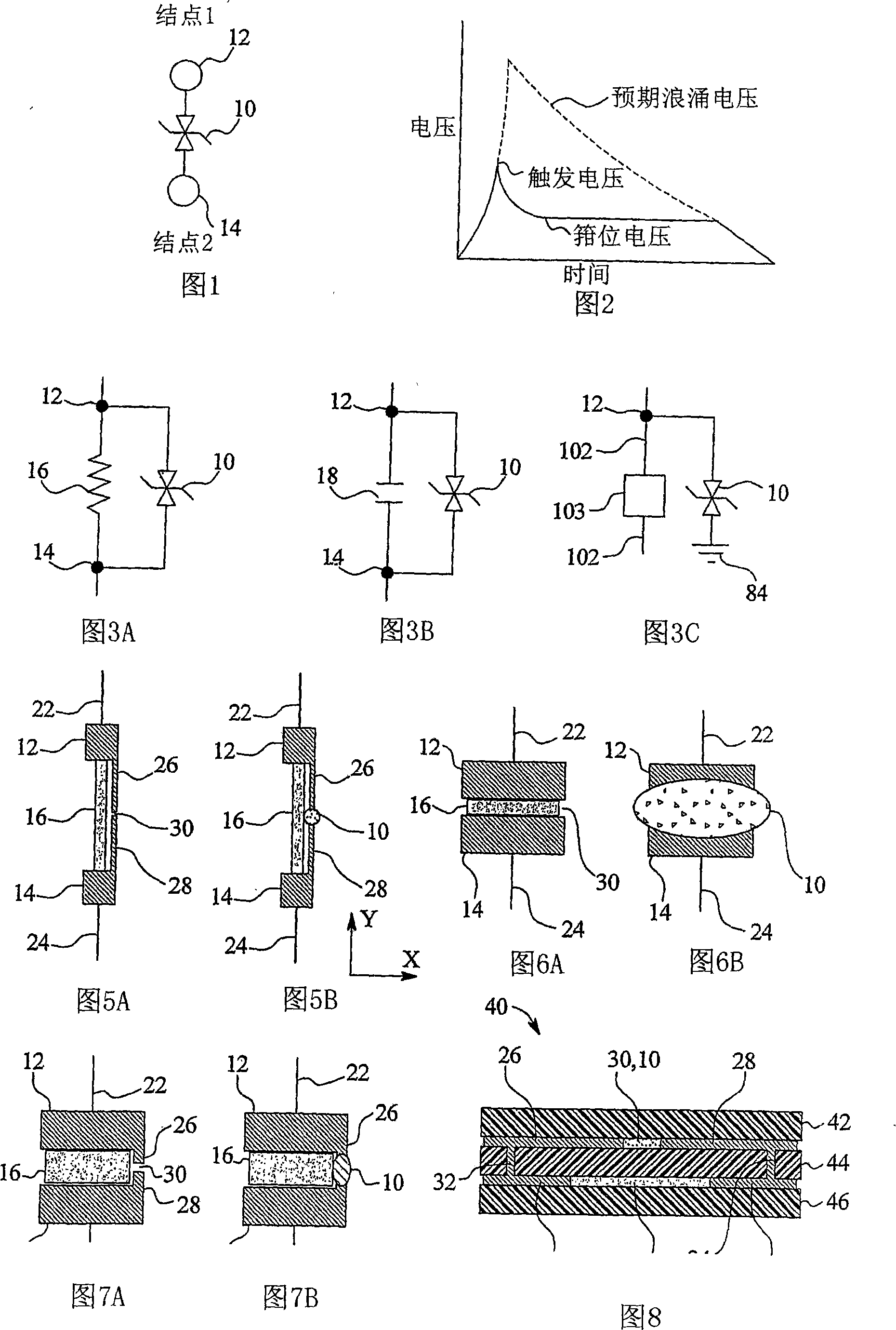
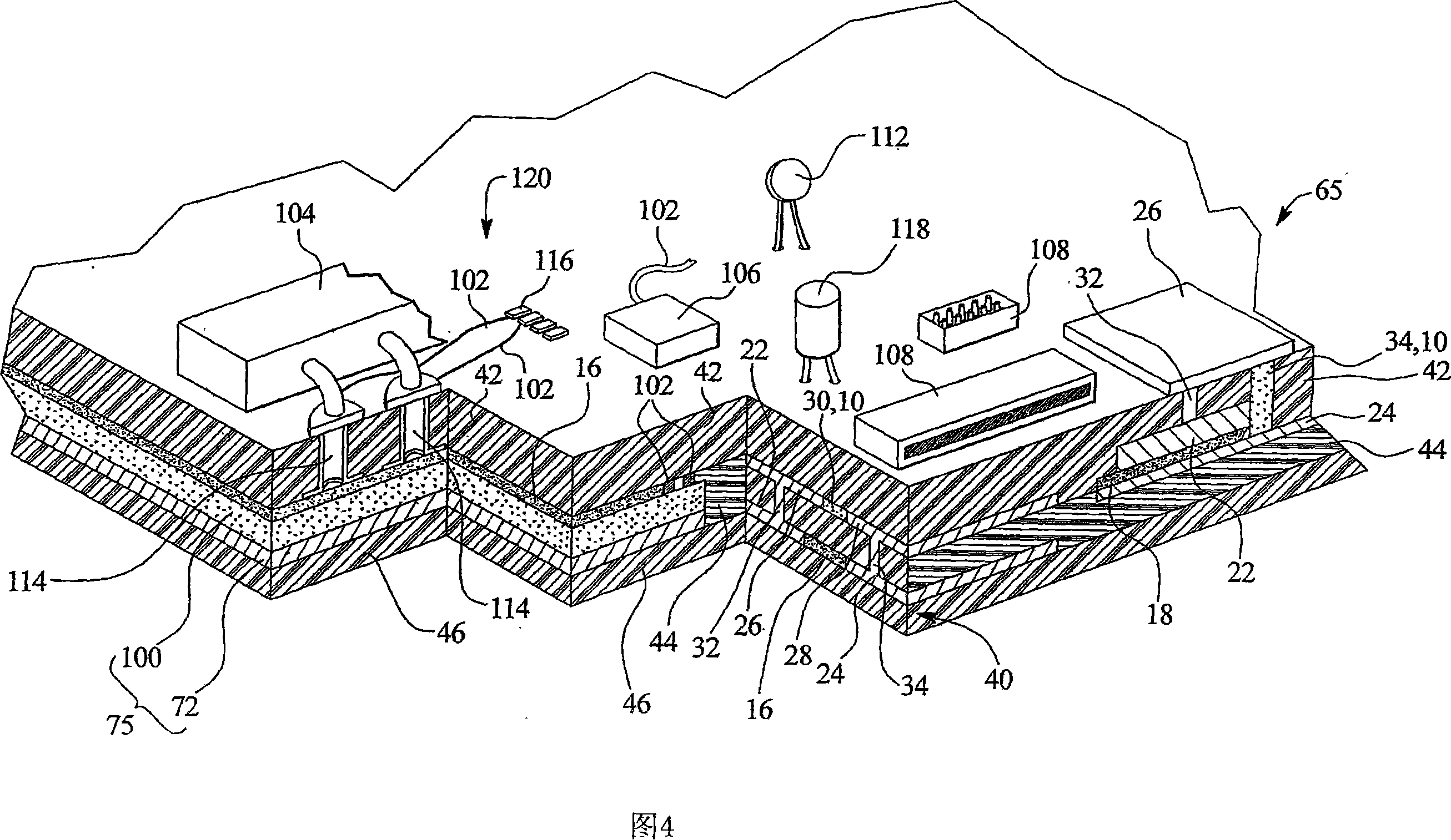
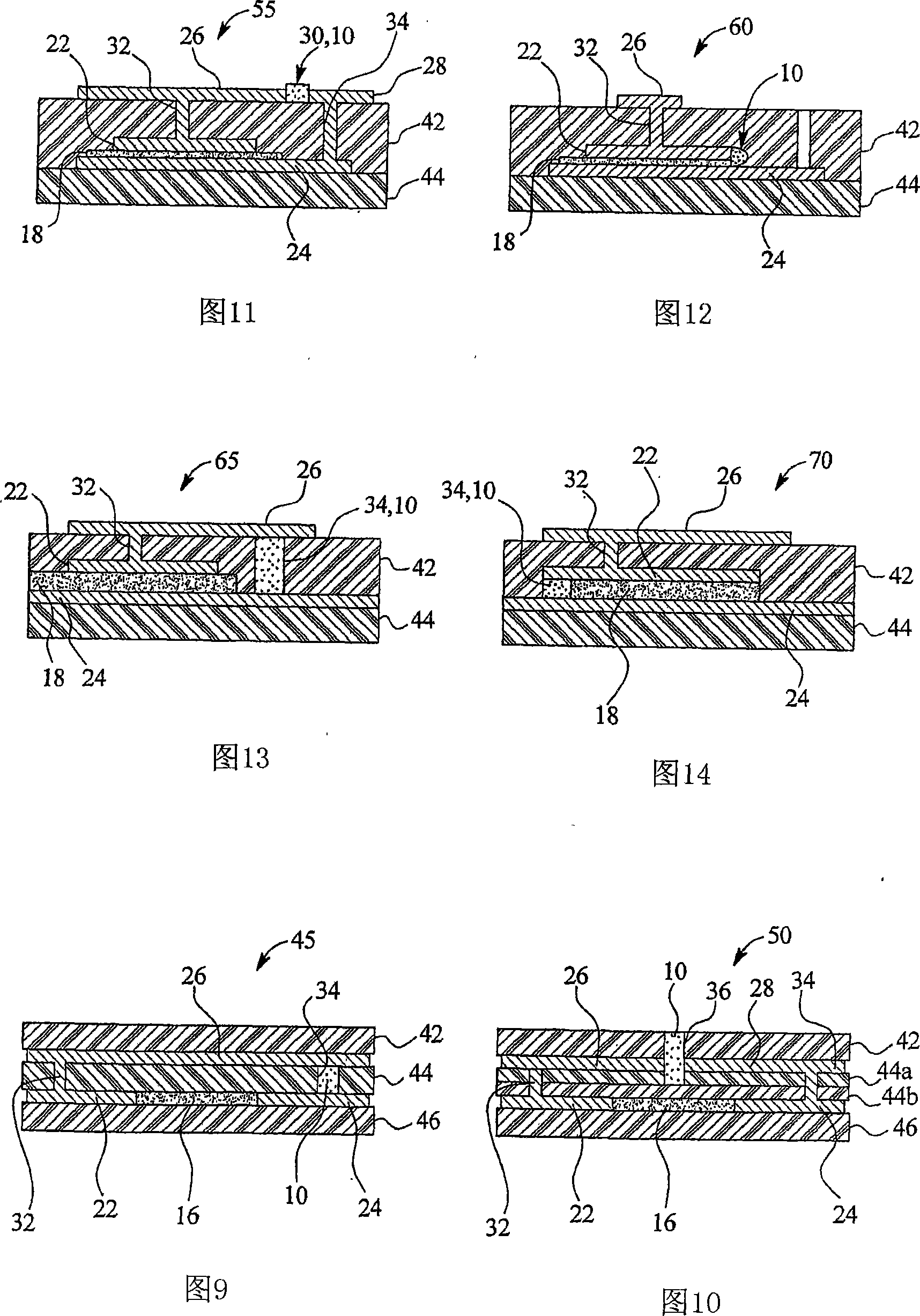
[0034] In a main embodiment of the invention, electrical components such as resistors and capacitors are embedded in a printed circuit board (PCB), such as a multi-layer PCB, using voltage variable material (VVM). In an embodiment, the electrical component is provided as a thin film laminated on an insulating substrate of a PCB or between two insulating substrates. The VVM is also laminated to an insulating substrate, such as the side opposite to the side where the piezoelectric element film is layered on the substrate. The combination of insulating substrate, component film and VVM can be provided as a device or a PCB capable of receiving circuit traces, surface mount components, through-hole components and other parts.

[0035] Embedded components and VVM reduce the overall size and cost of the resulting device or PCB. Embedded components and VVM also free up space on the outside of the PCB, such as on the upper and lower sides, and improve signal integr...


PUM


Abstract

An improved electrical circuit that includes an embedded electrical component and an embedded voltage variable material (''VVM'') is provided. In one embodiment, the embedded VVM is provided as a voltage variable substrate, which is used in combination with an embedded electrical component, such as an embedded resistive material or an embedded capacitive material.

Description

Background technique [0001] The present invention relates to circuit protection. More specifically, the present invention relates to voltage variable materials (VVM). [0002] Electrical overload transients (EOS transients) generate high electric fields and high peak powers that can temporarily or permanently disable a circuit or highly sensitive electronic components in a circuit. EOS transients may include transient voltage or current conditions capable of interrupting circuit operation or simply destroying a circuit. For example, EOS transients can result from electromagnetic pulses, electrostatic discharges, lightning, static current buildup, or by the operation of other electronic or electrical components. EOS transients can reach their maximum amplitude within sub-nanoseconds to microseconds and have repeated amplitude peaks. [0003] An electrostatic discharge transient (ESD event) can have a peak amplitude in excess of 25,000 volts while having a current greater tha...

Claims


Application Information

Patent Timeline
Patent Type & Authority Applications(China)
IPC IPC(8): H01C7/10
CPCH05K3/4652H05K1/167H05K3/4688H05K1/165H05K2201/09509H05K2201/0738H05K3/4069H05K1/0259H05K1/162H05K1/0373H05K3/4626H05K2201/0187H05K1/16H05K3/4655H01C7/003H01C7/12H05K2201/0215
Inventor 纳撒尼尔·梅尔克林图沙尔·维亚斯蒂莫西·帕赫拉斯蒂芬·惠特尼
Owner LITTELFUSE INC
Learn More