Display plate for solar cell apparatus and method of producing display plate for solar cell apparatus
A technology of solar cells and manufacturing methods, applied to mechanical devices for time indication, visually indicating time, circuits, etc., can solve the problems of poor quality yield, high manufacturing cost, and operational problems, and achieve the goal of manufacturing Effects of low cost, low equipment cost, and fewer manufacturing steps
- Summary
- Abstract
- Description
- Claims
- Application Information
AI Technical Summary
Problems solved by technology
Method used
Image
Examples
Embodiment 1
[0289] 3 is a cross-sectional view of key parts of Example 1 of a display panel for solar cell equipment according to the present invention, FIG. 4 is an explanatory diagram of the reflective polarizer in FIG. 3 , and FIG. 5 is an explanatory diagram illustrating the function of the reflective polarizer in FIG. 3 .
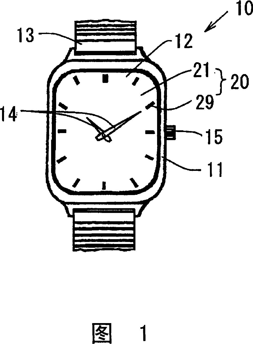
[0290] As shown in FIG. 3, reference numeral 20 denotes a display panel 20 for a solar timepiece incorporated in the solar timepiece 10 as described above (hereinafter simply referred to as a "display panel for a timepiece").
[0291] The components of this timepiece display panel 20 include: a light transmissive substrate 21, a first transmissive colored film 22 provided on the upper surface of the light transmissive substrate 21, and a first transmissive colored film 22 provided on the lower surface of the light transmissive substrate 21. The reflective polarizer 25 as a light transmissive reflective plate on the side.
[0292] A mark is attached to the upper s...
Embodiment 2
[0326] Fig. 6 is a sectional view of key parts of Embodiment 2 of a display panel for solar cell equipment according to the present invention.
[0327] As shown in FIG. 6, in the display panel 30 for a timepiece of this embodiment, a first transmissive colored film 32 is formed on the upper surface of a light transmissive substrate 31, and a transparent film 33 is formed on the upper surface of the first transmissive colored film 32. . Then, on the lower surface side of the light-transmitting substrate 31, a reflective polarizing plate 35 as a light-transmitting reflection plate is provided.
[0328] Therefore, the components of the timepiece display panel 30 of this embodiment include a light-transmitting substrate 31, a first transmissive colored film 32 formed on the upper surface of the light-transmitting substrate 31, a transparent film 33, and an Reflective polarizer 35 on the lower surface side of substrate 31.
[0329] The reflective polarizer 35 of this embodiment u...
Embodiment 3
[0342] Fig. 7 is a sectional view of key parts of Embodiment 3 of a display panel for solar cell equipment according to the present invention.
[0343] As shown in FIG. 7, in the watch display panel 40 of this embodiment, the prism reflection surface 41a is formed on the lower surface of the light-transmitting substrate 41, and the first transmissive surface 41a is also formed on the upper surface of the light-transmitting substrate 41. Colored film 42 . Further, a second transmissive colored film 46 is formed on the upper surface of the reflective polarizer 45 as a light transmissive reflective plate.
[0344] Therefore, the components of the timepiece display panel 40 of this embodiment include a light-transmitting substrate 41, a first transmissive colored film 42 formed on the upper surface of the light-transmitting substrate 41, a reflective polarizer 45, and a The second transmissive colored film 46 on the upper surface of the reflective polarizer 45 .
[0345] The lig...
PUM
| Property | Measurement | Unit |
|---|---|---|
| Thickness | aaaaa | aaaaa |
| Thickness | aaaaa | aaaaa |
| Thickness | aaaaa | aaaaa |
Abstract
Description
Claims
Application Information
 - R&D
- Intellectual Property
- Life Sciences
- Materials
- Tech Scout
- Unparalleled Data Quality
- Higher Quality Content
- 60% Fewer Hallucinations
Browse by: Latest US Patents, China's latest patents, Technical Efficacy Thesaurus, Application Domain, Technology Topic, Popular Technical Reports.
© 2025 PatSnap. All rights reserved.Legal|Privacy policy|Modern Slavery Act Transparency Statement|Sitemap|About US| Contact US: help@patsnap.com


