
Adaptive scanning optical microscope

An optical microscope and adaptive technology, applied in the direction of microscope, optics, optical components, etc., can solve the problems that cannot be adopted, and achieve the effect of reducing complexity

Active Publication Date: 2008-01-30
RENESSELAER POLYTECHNIC INST
View PDF11 Cites 21 Cited by
  • Summary
  • Abstract
  • Description
  • Claims
  • Application Information

AI Technical Summary

Problems solved by technology

In biological applications, this method cannot be used in many cases due to the consideration of photo damage, bleaching, and fluorescence.

Method used


Image

  • Adaptive scanning optical microscope
  • Adaptive scanning optical microscope
  • Adaptive scanning optical microscope

Examples


Embodiment Construction

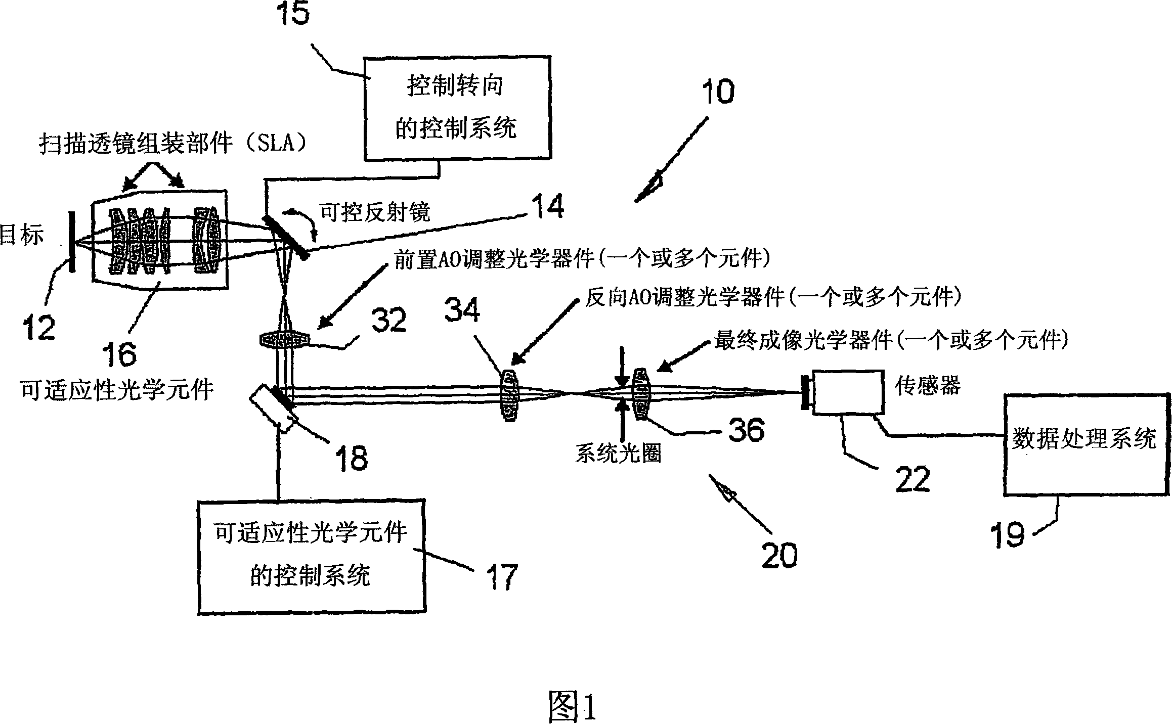
[0045] With reference to the drawings and numbers illustrating the same or similar elements therein, FIG. 1 shows an adaptive scanning optical microscope ASOM 10 in a mode of operation by sequentially sequentially spatially shifting images of objects 12 which are then combined into a large Composite images (mosaics) are either several separate or possibly overlapping images.

[0046]While the general concept of expanding the field of view while maintaining high resolution is well known, it has been used in biological imaging (see J. Zemek, C. Monks, and B. Freiberg, "Discoveries in an Automated State", Biophotonics International 10 , 54-57 (2003)) and industrial imaging (see C. Guestrin, F. Cozman, and S. Godoy, "Industrial Applications of Imaging Mosaics and Stabilization", Proceedings of IEEE International Conference on Knowledge-Based Intelligent Electronic Systems-Institute of Electrical and Electronics Engineers, New York, 1998, vol.2, pp.174-183), which replaces the comm...


PUM


Abstract

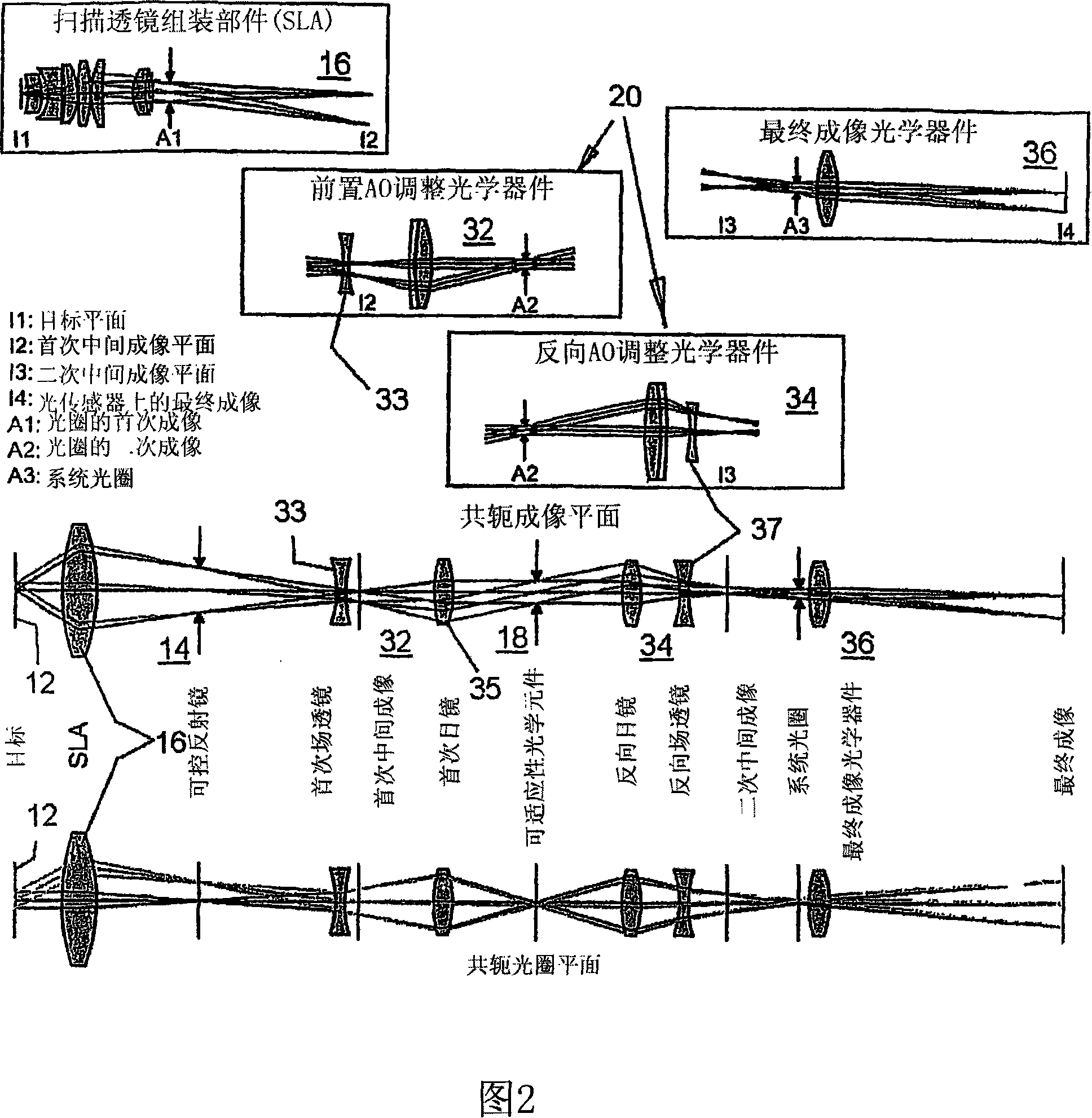
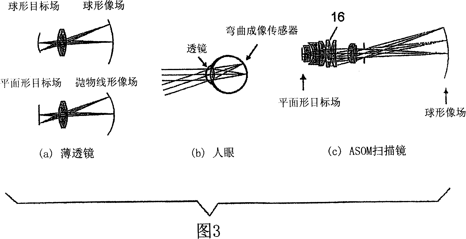
The invention relates to an adaptive scanning optical microscope. In this adaptive scanning optical microscope, a scanning lens assembly is installed, which can acquire images from different parts of the target plane, and then form a more suitable curved image field. In the resulting image field there will be at least some aberrations which vary as a function of the position of the imaging site on the object plane. A control mirror selects the imaging site and steers light from the object plane along an optical path from the object plane to the imaging plane. An adaptive optic receives light from the target, steers it, and compensates for aberrations that depend on the imaging position. There are additional optical devices on at least part of the optical path, and the optical devices will adjust and focus the light during the running process of the light from the control mirror, through the adaptive optical element, and finally to the imaging plane.

Description

[0001] Cross References to Related Applications [0002] This application claims priority to US Provisional Patent Application No. 60 / 647,572, filed January 27, 2005, which is hereby incorporated by reference. technical field [0003] The invention belongs to the related field of optical microscopes, in particular, the invention relates to a new adaptable optical microscope with application value. The present invention addresses and improves upon the balance between resolution and observation range that conventional optical microscopes have. Background technique [0004] In order to solve the problem of balance between resolution and observation range usually possessed by optical microscopes, the inventor disclosed a solution in US Patent Application No. 10 / 525,422 filed on February 25, 2005. This application claims priority to US Provisional Patent Application No. 60 / 411,038 and International Application No. PCT / US2003 / 029332, published as WO2004 / 025331, which are hereby i...

Claims


Application Information

Patent Timeline
IPC IPC(8): G02B26/08G02B21/36G02B21/06
CPCG02B21/367G02B26/06G02B21/0024
Inventor 本杰明·迈克尔·波特赛德伊夫·贝鲁尔德约翰·T·文
Owner RENESSELAER POLYTECHNIC INST
Learn More