
Process for improving the accuracy of manufacturing of precision boring head

A technology for manufacturing precision and boring heads, applied in boring heads, manufacturing tools, metal processing mechanical parts, etc., can solve problems such as difficulty in meeting precision requirements, low manufacturing precision of precision boring heads, and little consideration of errors. Overall manufacturing accuracy, satisfying the effect of boring processing and improving manufacturing accuracy

Inactive Publication Date: 2008-01-30
DALIAN HUAGEN MACHINERY
View PDF0 Cites 3 Cited by
  • Summary
  • Abstract
  • Description
  • Claims
  • Application Information

AI Technical Summary

Problems solved by technology

[0002] The precision boring head device is the main part of the precision boring machine. At present, the traditional method of assembling the precision boring head is relatively simple, just install the parts directly according to the assembly drawing, and seldom consider and deal with the problems generated in the process of processing the parts in time. Errors, such as the shape and position tolerances of the front and rear bearing holes, whether the elastic force of each stressed spring is uniform, and the ability of the spindle to withstand axial force after assembly, etc. This simple assembly makes the overall manufacturing of precision boring heads The precision is not high, and it is difficult to meet the precision requirements when using it to bore workpieces with high precision requirements such as the cylinder bore on the engine block

Method used


Image

  • Process for improving the accuracy of manufacturing of precision boring head
  • Process for improving the accuracy of manufacturing of precision boring head
  • Process for improving the accuracy of manufacturing of precision boring head

Examples


Embodiment Construction

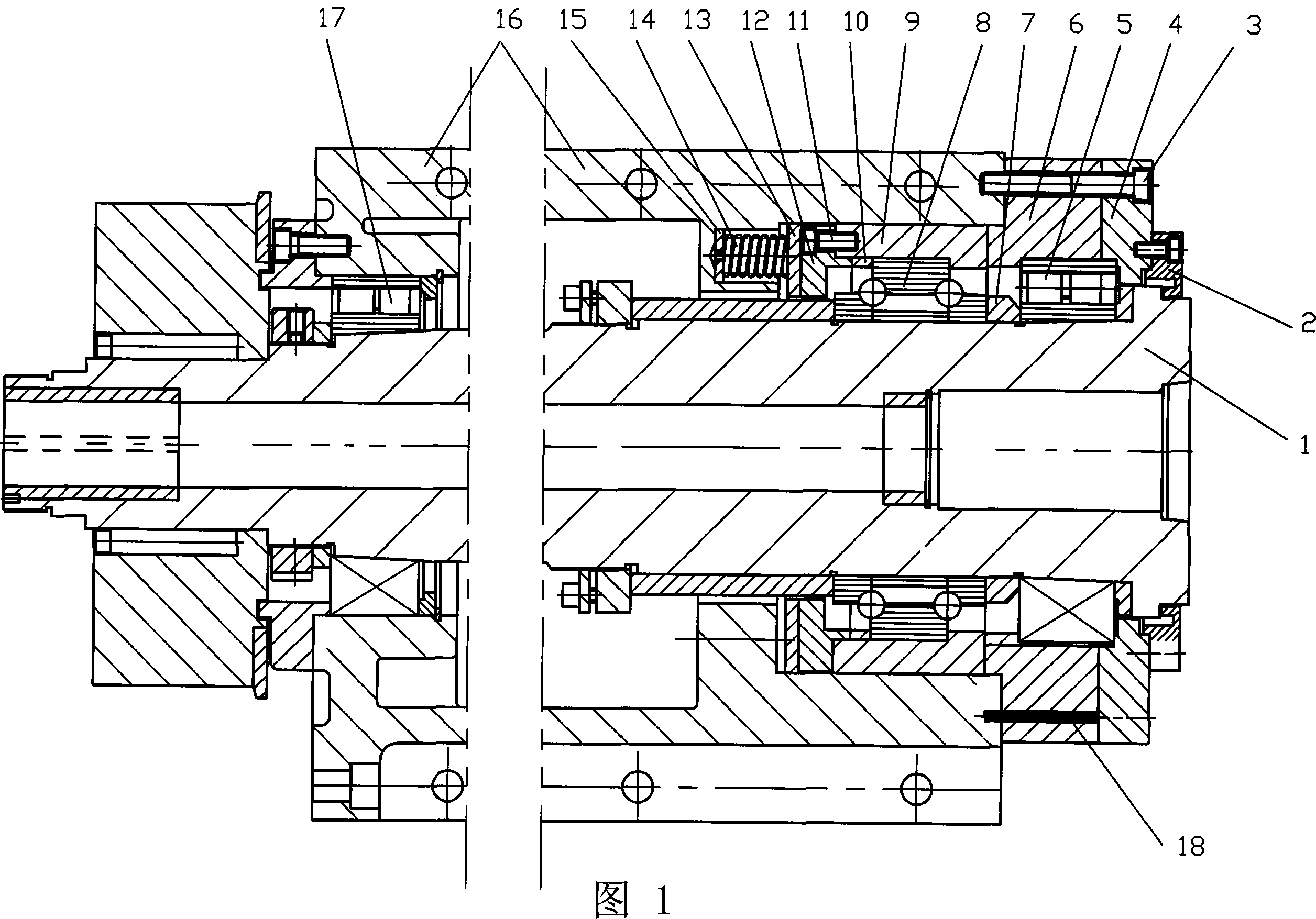
[0019] As shown in Figure 1: 16 is the main shaft housing, adopts casting process and machining molding. Front bearing sleeve 6 and gland 4 are fixed with bolt 3 at the right end of main shaft case 16, main shaft 1 is supported on main shaft case 16 with front bearing 5, intermediate bearing 8, rear bearing 17; The end cover 2 is connected; the intermediate bearing sleeve 9 is provided between the intermediate bearing 8 and the main shaft housing 16; the positioning ring 7 is set on the main shaft 1 between the front bearing 5 and the intermediate bearing 8; the bearing cover 12 is fixed by bolts 11 It is connected to the intermediate bearing sleeve 9 and is provided with a positioning ring 10 between the intermediate bearing 8 and the bearing cover 12; on the inner circumference of the main shaft housing 16, blind holes placed in the spring 14 are evenly distributed, and the washer 13 is located at the right end of the spring 14 Between the bearing cover 12, the left end of t...


PUM


Abstract

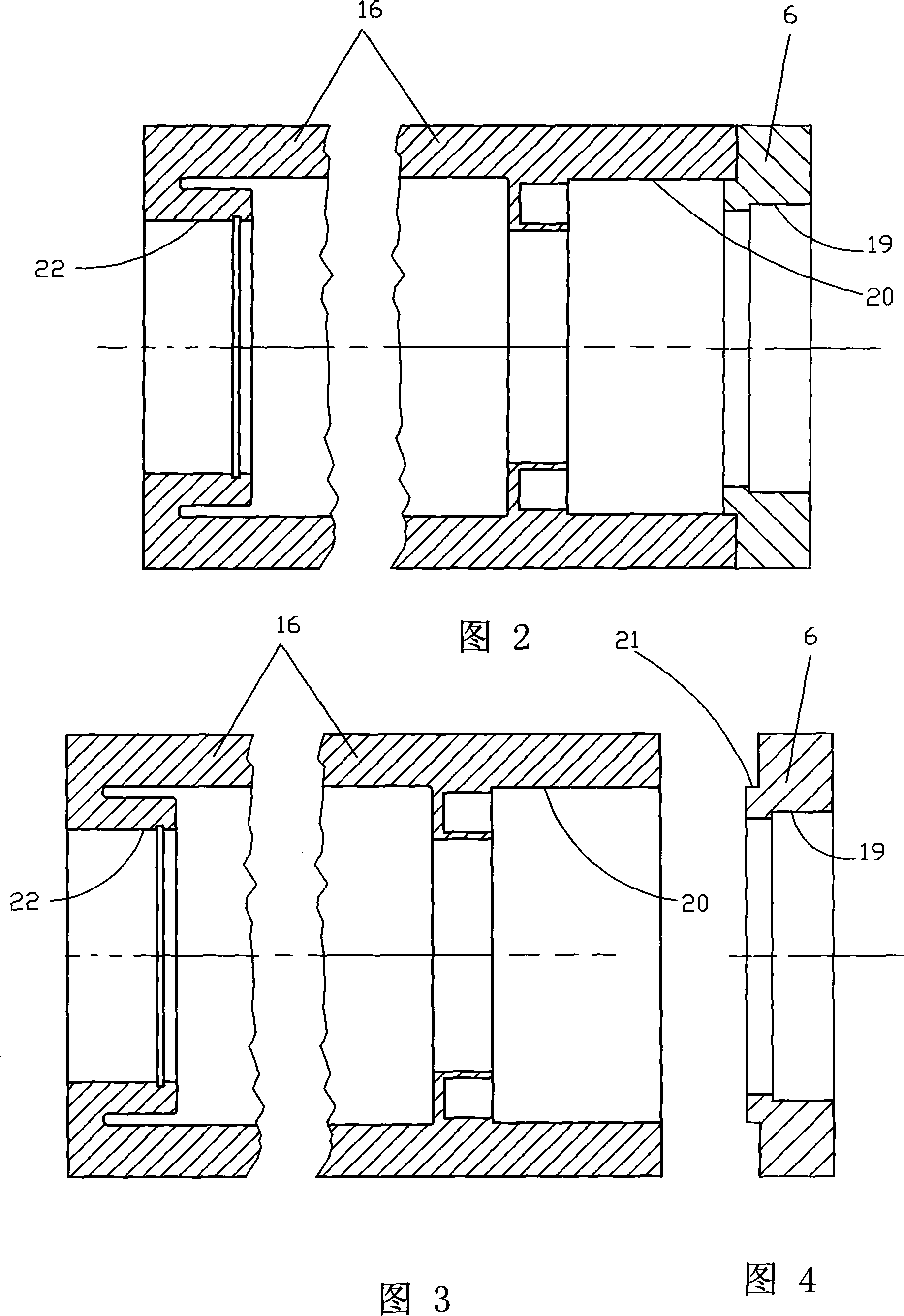
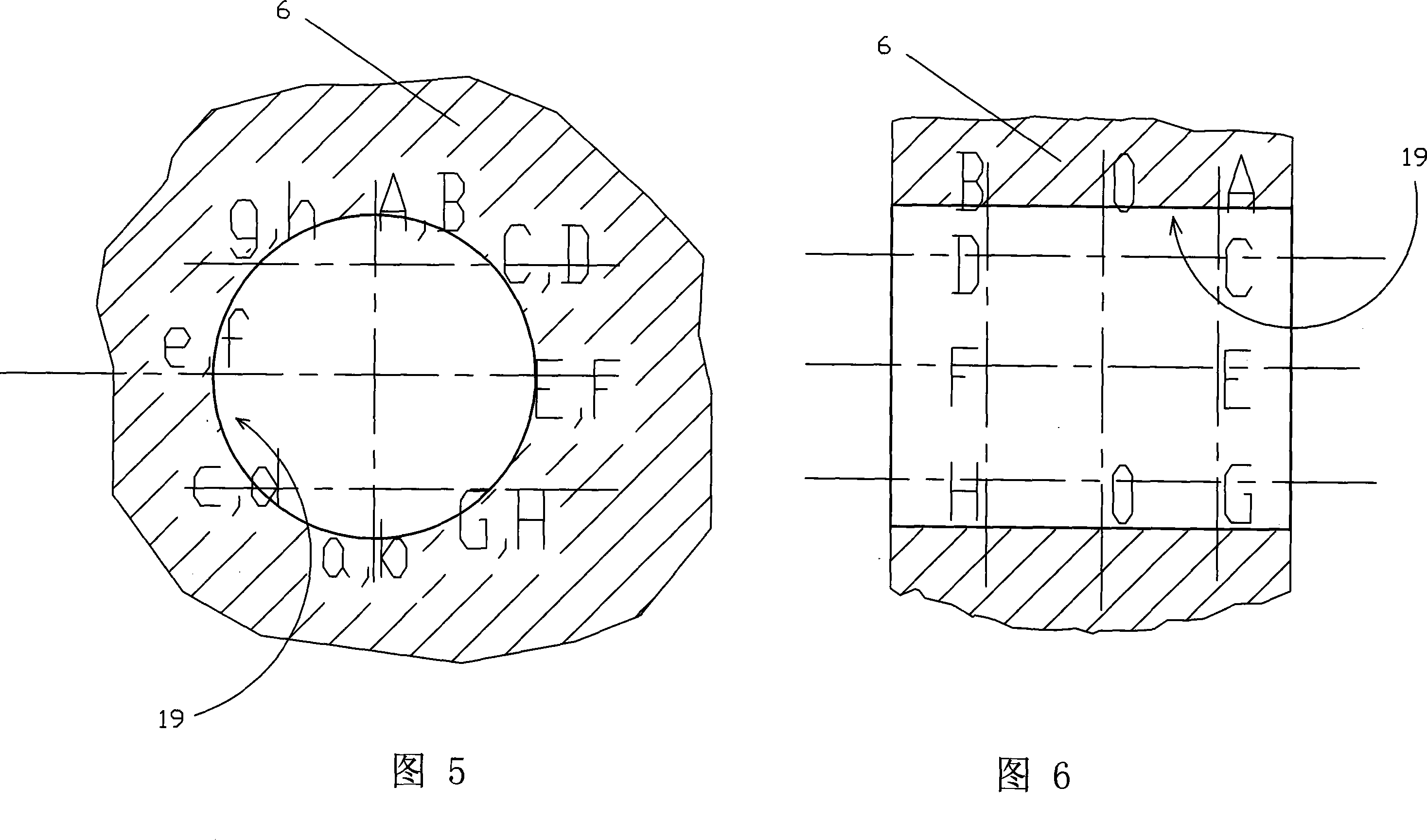
A method improving the manufacture precision of precision boring head includes the steps that the secondary aging treatment is carried out after the roughing process is carried out to a main shaft box body (16); the half-precision process is carried out to the main shaft box body (16), and a front bearing hole (20) and a rear bearing hole (22) are preserved with the processing allowance ranging from 0.05 mm to 0.06 mm; after the inspection is approved, the main shaft box body (16) is finish machined into the finished products according to the design requirement; the hole diameter of the front bearing hole (20) is actually measured; a spigot external round (21) on a front bearing sleeve (6) is matched and grinded according to the actually measure values; the geometric tolerance of the internal hole (19) of the front bearing sleeve (6) is actually measured, and the manual grinding disposal is adopted when the actually measured numerical values are oversize in the fourth step to reach the design requirement; a positioning pin (18) is adopted for positioning between the main shaft box body (16) and the front bearing sleeve (6). By adopting the method, when all work pieces are processed, the problems produced are timely and reasonably solved, and the integration manufacture precision of the precision boring is improved, and the boring process of the high precision work pieces can be satisfied.

Description

technical field [0001] The invention relates to a method for improving the precision of machining equipment, in particular to a method for improving the manufacturing precision of a precision boring head. Background technique [0002] The precision boring head device is the main part of the precision boring machine. At present, the traditional method of assembling the precision boring head is relatively simple, just install the parts directly according to the assembly drawing, and seldom consider and deal with the problems generated in the process of processing the parts in time. Errors, such as the shape and position tolerances of the front and rear bearing holes, whether the elastic force of each stressed spring is uniform, and the ability of the spindle to withstand axial force after assembly, etc. This simple assembly makes the overall manufacturing of precision boring heads The accuracy is not high, and it is difficult to meet the accuracy requirements when using it to ...

Claims


Application Information

Patent Timeline
Patent Type & Authority Applications(China)
IPC IPC(8): B23B29/03B23B19/00B23Q17/00
Inventor 孙德明陈永龙邵奎建张树礼薛孺牛
Owner DALIAN HUAGEN MACHINERY
Learn More