
Fluid energy converting device

An energy conversion device and fluid technology, which is applied in the field of fluid energy conversion devices and mechanical energy devices, can solve the problems of inability to adjust the force size and force area, no self-protection function, and the air door cannot return to the original state by itself. The effect of simple and reasonable structure, simple structure and ingenious conception

Inactive Publication Date: 2008-01-23
蔡志凌
View PDF1 Cites 6 Cited by
  • Summary
  • Abstract
  • Description
  • Claims
  • Application Information

AI Technical Summary

Problems solved by technology

The damper of this utility model patent rotates left and right on the horizontal plane. Under special circumstances, the damper can be blown to a position where it cannot rotate, and the damper cannot return to the original state by itself, and the force and force area cannot be adjusted. self-protection function

Method used


Image

  • Fluid energy converting device
  • Fluid energy converting device
  • Fluid energy converting device

Examples


Embodiment Construction

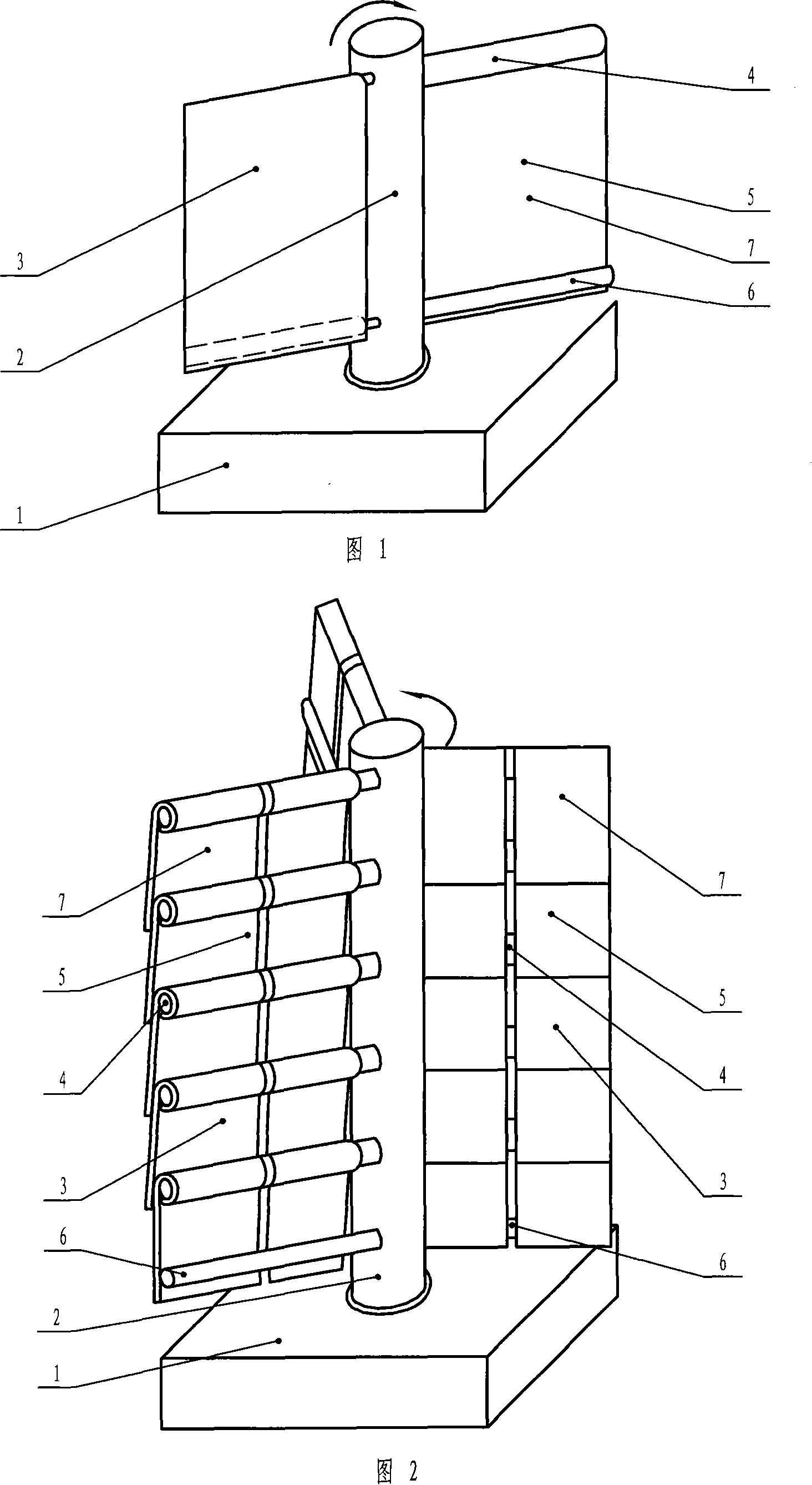
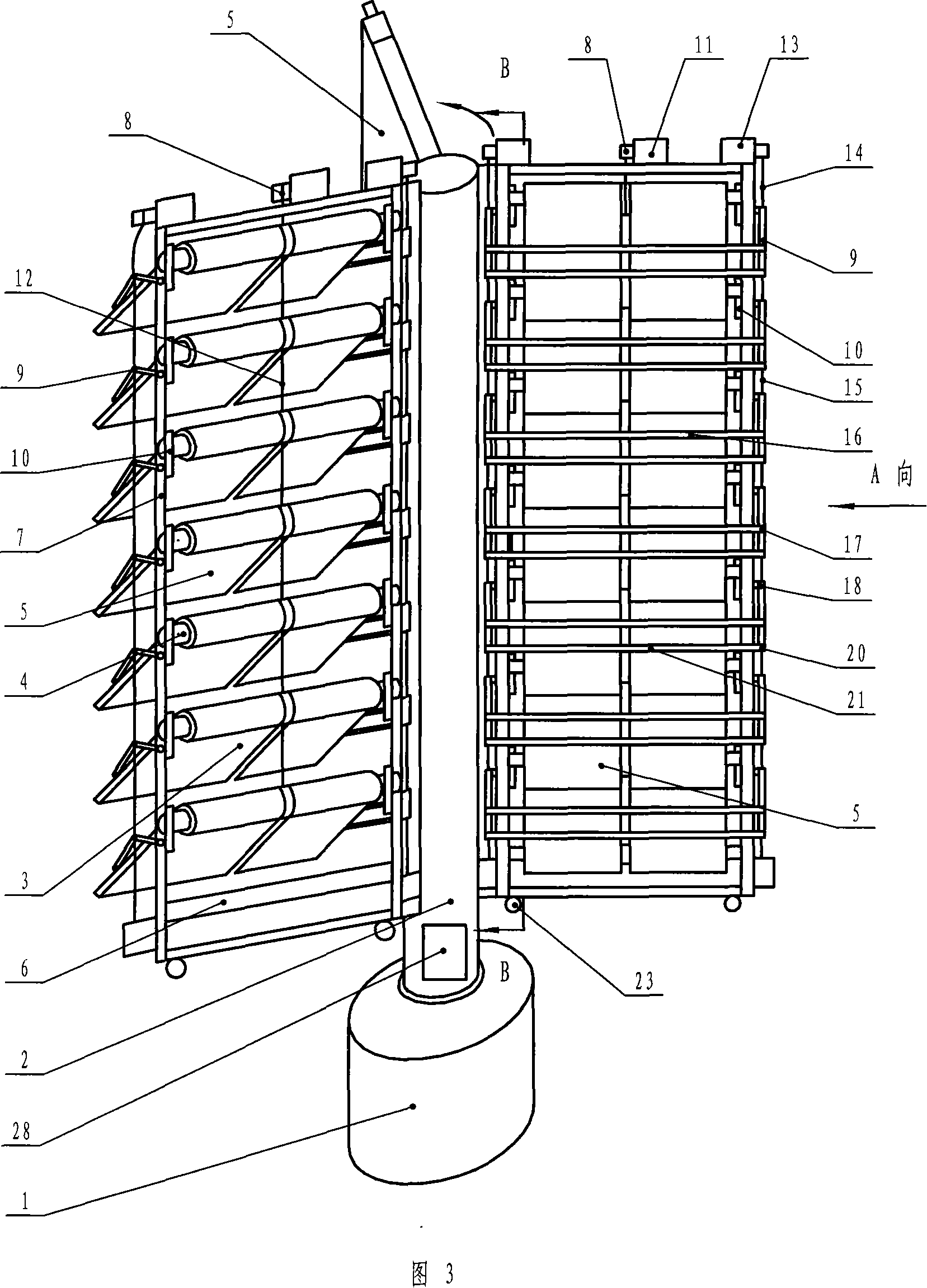
[0026] Fig. 1 is a three-dimensional schematic diagram of the structure of the first embodiment of the fluid energy conversion device of the present invention, the device is composed of a machine base 1, a main shaft 2, a rotating body 3, a horizontal shaft 4, a longitudinal rotating blade 5 and a crossbar shaft 6, the figure The main shaft 2 is rotatably fixed on the machine base 1, and the sides of the main shaft 2 are fixed to each other with a rotating body 3. Each rotating body 3 includes: a horizontal shaft 4 perpendicular to the main shaft 2 and fixed, and a set of horizontal shafts. The shaft 4 is a vertically rotating blade 5 that rotates longitudinally and a crossbar shaft 6 that blocks the bottom of the longitudinally rotating blade 5 and is perpendicular to the main shaft 2. The structure of each rotating body 3 is: the crossbar shaft 6 is from top to bottom Look at the bottom of the upper longitudinal rotating blade 5 blocked in the clockwise direction, the longitu...


PUM


Abstract

The invention relates to an energy converter for fluid, pertains to the technical field of energy conversion, which can convert the kinetic energy of a fluid in any direction into mechanical energy for rotating in oriented way about a rotary shaft by the following propose: a fluid energy converter, a rotatable main shaft and at least two rotating parts that are isolated each other and drive the main shaft to rotate in the same direction and rotate about a cross shaft that is vertical to the main shaft, a rotating part comprises at least one cross shaft that is vertical to the main shaft and fixed, at least one group of longitudinally rotating blades that rotate about the cross shaft and a cross baffling shaft that baffles the longitudinally rotating blade at the lowest point and is vertical to the main shaft. The invention can take use of wind, water flow, wave, tide, pressure oil and steam for generating power, irrigation and transportation, etc., and is of a wonderful market prospect.

Description

technical field [0001] The fluid energy conversion device of the present invention specifically relates to a device capable of converting fluid kinetic energy in any direction into mechanical energy for directional rotation around a certain rotating shaft, and belongs to the technical field of energy conversion. Background technique [0002] At present, the development of new energy and renewable energy is still in its infancy. It mainly obtains energy through solar energy, water energy, wind energy, chemical energy and atomic energy. These energy sources such as chemical energy and atomic energy have certain pollution and pollution at the current stage. Harm, while the use of solar energy, water energy and wind energy is more common, and the utilization of solar energy, water energy or wind energy is easily affected by time, region and other factors, especially the use of water energy and wind energy is affected by the direction of water flow or wind As for water energy, el...

Claims


Application Information

Patent Timeline
Patent Type & Authority Applications(China)
IPC IPC(8): F03D3/06
CPCY02E10/74
Inventor 蔡志凌
Owner 蔡志凌
Learn More